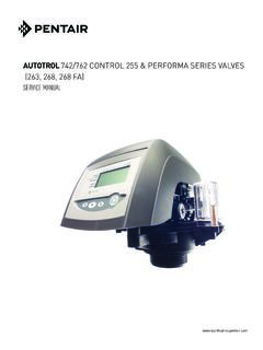
Transcription of 740/760 Control 255 and Performa Series Valves (268, 268FA)
1 740/760 Control255 and Performa SeriesValves (268, 268FA) Operation ManualFor Sales & Service questions please contact your dealer:Your local dealer is:2 TABLE OF CONTENTSRev ETABLE OF CONTENTSLOGIX Series INSTALLER QUICK-START SHEET3 MANUAL OVERVIEW7 How To Use This Manual7 EQUIPMENT INSTALLATION8 General Warnings And Safety Information8 Valve Features11 Location Selection13 Water Line Connection14 Drain Line Connection16 Overflow Line Connection17 Regenerant Line Connection18 Electrical Connection20 Valve Camshaft21 SYSTEM DISINFECTION23 Disinfection Of Water Conditioners23 DETERMINING IF YOU HAVE A 740 OR 760 CONTROL24 GENERAL 700 Series INSTRUCTIONS25 DISPLAY ICONS 700 CONTROLLERKEYPAD Buttons28 Regeneration Modes29740/760 Series Initial Power-Up30
2 Initial Start-up Step-By-Step Instructions31 PLACING CONDITIONER INTO OPERATION (turning on the water)34 PROGRAMMING THE 700 FOR 5-CYCLE FILTER APPLICATIONS37 Manganese Greensand Systems37700 Series Advanced Programming39 Resetting the Logix Control40740/760 PROFESSIONAL PROGRAMMING41 VALVE SERVICE43 Cover43 Electronic Control Module43 Drive Motor44 Optical Sensor45 Camshaft46 Wiring Harnesses48 Microswitch (Optional Under the Cover)49 Microswitch (Optional - Front of Camshaft)50 Spring (Valve Discs)51 Relay (Optional)52 Terminal Block (Optional)53 Transformer (Optional)53 Top Plate54 PARTS AND ACCESSORIES56255 Valve Exploded View56255 Valve Parts List57 Performa Exploded View59 Performa Parts List60 Logix 700 Series Controllers Parts List61 TROUBLESHOOTING62 LOGIX Series INSTALLER QUICK-START SHEET3 Rev EQUICK STARTLOGIX Series INSTALLER QUICK-START SHEETL ogix Series ControllersSee Determining If You Have a 740 or 760 Control on page 24 to identify your Controller - Electronic time clock Control capable of doing 7-day (day of week) regeneration, or up to a 99 interval day regeneration.
3 This Control will operate both in a conditioner (softener) or 3-cycle filter mode with the same Controller - Electronic metered-demand (volumetric) controller which regenerates based on the water usage of the installation site. A calendar override is a standard feature on this controller. The Logix Series will operate on both the 255 and Performa valve body Power-upInitial Power Up - (CAMSHAFT proceeds to HOME position) At initial power-up, the camshaft will need to rotate to the HOME (in service) position. Camshaft may take 1-2 minutes to return to home position. Err 3 will be displayed until the camshaft returns to home.
4 If more than 2 minutes elapses, verify that the motor is turning the camshaft. If it is not turning, see the troubleshooting & DayRegen Time & DaySaltSU MO TU WE TH FR SA DAYSLBSPMMINKGx100x2 PHCC apacityHardnessManual RegenerationUP ButtonSET ButtonDOWN ButtonLCD DisplayTime & DayRegen Time & DaySaltCapacityHardnessSU MO TU WE TH FR SA DAYSNOTE: The Logix controller features a self-test sequence. At first power-up of the Control , you may see a number such as , , , or , displayed. This is an indication that the self-test is not completed. To complete the test, verify that the turbine cable is connected.
5 Blow into the turbine port (valve outlet) to spin the turbine. The controller will verify that the turbine works and the self test will finish. Proceed with the initial start up procedure. 4 LOGIX Series INSTALLER QUICK-START SHEETRev EQUICK STARTI nitial Start-up Step-by-step InstructionsStep 1: Program System SizeThis step may have been performed by your system s OEM manufacturer. In this case, proceed to step 2. Input system size - resin volume - in cubic feet or liters. Use UP and DOWN buttons to scroll through resin volume choices. Choose the nearest volume to your actual system size. To choose a 3-cycle filter operation - press DOWN until an "F" is displayed.
6 Press SET to accept the system size you ve selected. If incorrect setting is programmed, see "Resetting the Control " section 2: Program Time of Day While "12:00" is blinking, set the correct time of day. Use the UP and DOWN buttons to scroll to the correct time of day. "PM" is indicated, "AM" is not indicated. Press SET to accept the correct time of day and advance to the next 3: Set Day of Week Press SET to make the arrow under SU flash. Use the UP and DOWN buttons to advance the arrow until it is under the correct day of week. Press SET to accept and advance to the next steps 1-4, the controller will operate most systems.
7 Proceed to step 5 if further adjustments to your system s programming is exit the programming state, wait 30 seconds and the controller will automatically put you into the normal operating 4: Set Regen Time 2:00 (AM) is the default time of regeneration. To accept this time, press the DOWN button to move to step 5. To change the regen time, press SET - causing 2:00 to flash. Use the UP and DOWN buttons to advance to the desired regen time. Press SET to accept the time and advance to the next 5: Set Days to Regenerate (740 Time-clock Control Only) If using 760 Control - proceed to step 5a. Set number of days between time-clock regeneration (regen frequency).
8 Default time is 3 days. Days can be adjusted from 1/2 (.5) to 99 days. To change, press SET to make the "3" flash. Use the UP and DOWN buttons to change to the number of days desired. Press SET to accept the regen frequency, and advance to the next use the 7-day timer option - see full Dealer Installation 5a: Set Calendar Override (760 Demand Control Only) If using 740 Control - proceed to step 7. Set number of days for calendar override on demand Control . "0" days is the default for calendar override. Days can be adjusted from 1/2 (.5) to 99 days. To change, press SET to make the "0" & DayRegen Time & DaySaltSU MO TU WE TH FR SA DAYSC apacityHardnessTime & DayRegen Time & DaySaltSU MO TU WE TH FR SA DAYSC apacityHardnessTime & DaySU MO TU WE TH FR SA DAYSC apacityHardnessTime & DayRegen Time & DaySaltSU MO TU WE THFRSA DAYSC apacityHardnessTime & DayRegen Time & DaySaltSU MO TU WE TH FR SA DAYSC apacityHardnessTime & DayRegen Time & DaySaltSU MO TU WE TH FR SA DAYSC apacityHardnessTime & DayRegen Time & DaySaltSU MO TU WE TH FR SA DAYSC apacityHardnessLOGIX Series
9 INSTALLER QUICK-START SHEET5 Rev EQUICK START Use the UP or DOWN buttons to change to the number of days desired. Press SET to accept the regen frequency, and advance to the next 6: Amount of Regenerant used per Regeneration Set desired regenerant amount. Default setting is "S" standard salting. 3 salt settings are available on 740 and 760 controls:S Standard Salt 9 lbs/cubic foot of resin (120 grams/liter of resin)H High Salt 15 lbs/cubic foot of resin (200 grams/liter of resin)L Low Salt 3 lbs/cubic foot of resin (40 grams/liter of resin) Low Salt is the "Highly Efficient Mode". To change salt setting, press the SET button and use the UP and DOWN buttons to change to the desired setting.
10 Press SET to accept the setting and advance to the next Dealer Installation Manual for more complete information on salt settings for different system sizes, capacities and expected efficiencies. Step 7: Estimated Capacity System capacity is displayed in total kilograins or kilograms of hardness removed before a regeneration is necessary. Value is derived from the system s resin volume input, and salt amount input. The capacity displayed is a suggested value - as recommended by resin manufacturers. Capacity is only displayed for information purposes on 740 Control - it does not (and cannot) need to be changed.