Transcription of 8. STRENGTH OF SOILS AND ROCKS
1 8-1 8. STRENGTH OF SOILS AND ROCKS COMPRESSIVE STRENGTH The STRENGTH of a material may be broadly defined as the ability of the material to resist imposed forces. If is often measured as the maximum stress the material can sustain under specified loading and boundary conditions. Since an understanding of the behaviour in tension of a material such as steel is of great importance, the tensile STRENGTH of that material is normally measured and is used to compare one steel with another. In the case of soil, attention has been directed more towards the measurement and use of the shear STRENGTH or shearing resistance than towards any other STRENGTH parameter.
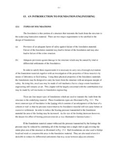
2 (Bishop, 1966). In the case of concrete, the compressive STRENGTH is the most commonly measured STRENGTH parameter and this is also true of rock specimens. For the uniaxial or unconfined compressive STRENGTH test a right circular cylinder of the material is compressed between the platens of a testing machine as illustrated in Fig. The compressive STRENGTH is then defined as the maximum load applied to crush the specimen divided by the cross-sectional area. Rock STRENGTH has been found to be size dependent because of the cracks and fissures that are often present in the material. This is illustrated from the results of tests on three rock types in Fig.
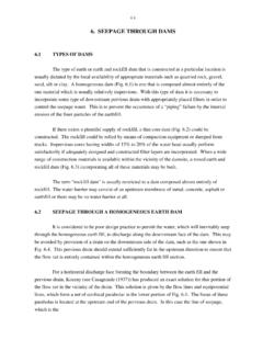
3 The size dependancy is also found to exist for stiff fissured clays, as illustrated in Fig. for London clay. ROCKS with parallel arrangements of minerals or joints have been found to be noticeably anisotropic (different strengths in different directions). This particularly applies to metamorphic ROCKS as illustrated in Fig. STRENGTH testing of rock is discussed further by Franklin and Dusseault (1989). TENSILE STRENGTH The tensile STRENGTH of soil is very low or negligible and in most analyses it is considered to be zero. In contrast a number of direct or indirect tensile STRENGTH tests are commonly carried out for rock. In a direct tensile STRENGTH test a cylindrical rock specimen is stressed along its axis by means of a tensile force.
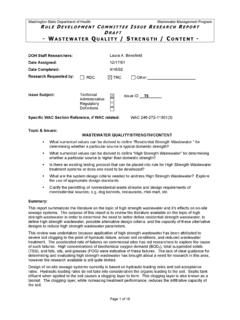
4 The tensile STRENGTH is then calculated as the failure tensile force divided by the cross-sectional area. It has been found that a rock core will split along a diameter when loaded on its side in a compression machine. This is the basis of the Brazilian test which is an indirect method of measuring tensile STRENGTH . A rock specimen having a disc shape with diameter (d) and thickness (t) is loaded as illustrated in Fig. If the failure load is P then the tensile STRENGTH ( t) is calculated from8-2 Fig. Unconfined Compression Test Fig. Effect of Specimen Size on Unconfined Compressive STRENGTH (after Bieniawski & Van Heerden, 1975) 8-3 Fig.
5 Effect of Sample Size on STRENGTH of London Clay (after Marsland, 1971) Fig. Effect of Anisotropy on STRENGTH of Slate (after Franklin & Dusseault, 1989) 8-4 t = 2P / ( d t) ( ) Generally the Brazilian test is found to give a higher tensile STRENGTH than that obtained in a direct tension test, probably because of the effect of fissures in the rock. Another method of determining tensile STRENGTH indirectly is by means of a flexural test in which a rock beam is failed by bending. Either three point or four point loading (Fig. ) may be used in the test. For a cylindrical rock specimen (diameter d) and the four point loading arrangement as shown in Fig.
6 , it may be shown that the tensile STRENGTH ( t) is t = 32 PL/(3 d3) ( ) where P is the failure load applied at each of the third points along the beam. For a beam of rectangular cross section (height h and width w) the tensile STRENGTH is t = 2 PL/(w h2) ( ) The tensile STRENGTH determined from beam bending tests is found to be two to three times the direct tensile STRENGTH . The point load STRENGTH test may be used to provide an indirect measurement of tensile STRENGTH , but it is more commonly used as an index test. The point loading is applied to rock core specimens or to irregular rock fragments in a testing machine. If P is the failure load and D is the separation between the platens, the point load STRENGTH index (Is) is defined as IS = P/D2 ( ) Corrections are applied to IS to allow for specimen size and shape to yield the size corrected point load STRENGTH index (IS50) which is defined as the value of IS for a diametral test with D equal to 50mm.
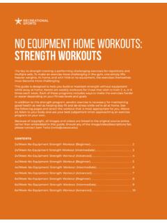
7 The value of IS50 is about 80% of the direct tensile STRENGTH . SHEAR STRENGTH OF SOIL One method of determination of the shearing resistance of a soil is similar to the procedure used to measure the coefficient of friction of a block sliding on a rough plane. This is illustrated in Fig. which shows the results of a number of tests in which a block loaded by a normal force N is pulled by a shear force T until the block slides on the plane. The shear force required to cause sliding is indicated by Tmax. The ratio of force Tmax to force N, which is the slope of the line drawn through the plotted points is the coefficient of friction. 8-5 Fig.
8 Brazilian Test Fig. Beam Bending Test8-6 Fig. Block Sliding on a Rough Plane Fig. Shear Stress - Diplacement Plots from Direct Shear Tests 8-7 The somewhat similar procedure that is used with soil is known as the direct shear test. For this test the soil sample is placed in a container in which one half can move relative to the other half thus imposing a shear stress on the sample. As the displacement in the direction of the shear force T of one half of the apparatus relative to the other half increases, the shear stress gradually builds up to a maximum value as illustrated in Fig. The maximum value of the shear stress is the shear STRENGTH of the soil for the particular value of the normal force N or normal stress (N/A) applied to the soil, where A is the cross sectional area of the soil sample.
9 Fig. shows that a dense sand has a greater shear STRENGTH than a loose sand and this STRENGTH is reached at a smaller value of the displacement. The results of a number of direct shear tests are shown in Fig. The sand yields a shear stress-normal stress plot similar to that of the sliding block in Fig. but the clay gives an intercept on the shear stress axis. The general equation of a straight line on this type of plot is max = c + tan ( ) in which c called the cohesion is the intercept on the shear stress axis called the friction angle or angle of shearing resistance indicates the slope of the line. Equation ( ) is generally referred to as the Coulomb equation and this equation (the subscript max is often deleted) is commonly used to describe the STRENGTH of SOILS .
10 The STRENGTH parameters c and may be expressed in terms of either total stresses or effective stresses. The lines (failure lines) plotted in Fig. are straight but with many SOILS the lines exhibit a slight curvature. In these cases a straight line approximation over the relevant range of normal stress values is normally used. It should be emphasised that a particular soil does not possess unique values of cohesion and friction angle. The values of the STRENGTH parameters c and depend upon the method of test as well as upon the soil type. Some of the commonly used methods of shear STRENGTH testing will be discussed in later sections of this chapter.