Transcription of 80-10 end-fed half-wave antenna with 49:1 unun - Noji
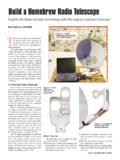
1 21 UVARC Shack July 2020 DIY Worthwhile projects you can build on your own 80-10 end-fed half-wave antenna with 49:1 unun Many hams in the club have asked about this antenna , because it s been such a good perform-er during Field Day, a Special Event Station, and at the 76ers Picnic. Many were just as amazed by its seeming simplicity and ease-of-installation, and wanted to build one for themselves, es-pecially because it employs only one wire, does not use traps, and does not require a tuner. This EFHW antenna (patterned after one by Steve Ellington N4LQ, with notes by K1RF), if built carefully, will serve you for many years, and at up to 200 watts. The heart and engineering of its design is in its 49:1 impedance matching transformer, or unun (connects an unbalanced feed line to an unbalanced radiating element,) where much of this DIY is focused.
2 The 132-foot half-wave radiating element presents about an 1800 ohm (at 10 meters) to 5000 ohm (at 80 meters) impedance to an end-fed feed point. The unun, therefore, matches it down between 1800 49 = 37 ohms and 5000 49 = 102 ohms. At worst case, 102 ohms 50 ohms = :1 SWR, well within tuner range; and in fact, should be very good without a tuner. Parts list One x x enclosure 140 feet 18 AWG wire Two toroidal FT240-43 ferrite cores 6 feet 14 AWG enameled magnet wire Two 220 pF 15 kV ceramic capacitors One 3/4 PVC slip coupling One SO-239 solder bulkhead Four mm x 14 mm machine screws One 1 #8-32 zinc-plated machine screw Four mm hex nuts One #8-32 wing nut Four M3 split washers One #8 flat washer One #4 x 18 AWG ring terminal One #8 split washer Two #8 x 18 AWG ring terminals Four 1 pieces of heat shrink tubing One 2 x 3 fiberglass screen One dogbone insulator Super Glue Construction Permanently glue together the two toroids into a single toroid.
3 Do NOT place tape or any other covering over the toroids. Cut the magnet wire into one 13-inch wire and one 51-inch wire. Lay the two wires together in paral-lel, with one of the ends even with the other. While pinching about an inch of the wires in a vise, pull-twist the two wires about 90 degrees from each other tightly into an 8-inch-long helix. 22 UVARC Shack July 2020 DIY, continued 80-10 end-fed half-wave antenna This is known as a bifilar ( two-filament ) pair. Place the junction of the long and short wires on the side of the toroid, and wrap two turns of the pair over the top and around one toroid arc. Continue wrapping the longer wire around the toroid arc for five more turns. After the fifth turn, thread the wire through the middle again, but continue winding on the op-posite side for seven turns.
4 Diagram by K1TA Our transformer 23 UVARC Shack July 2020 DIY, continued 80-10 end-fed half-wave antenna Install the SO-239 bulkhead connector on one end ( bottom ) of the enclosure. Drill a 1/8 hole on the side of the enclosure, at the other end, for the antenna wire to exit. I actually drilled a hole and glued a crimp sleeve (that brass thing) into it, because I had one lying around. (I also installed them into the flange holes, to protect the wire and support cord from the sharp edges of the enclosure holes.) Drill twelve to sixteen holes in the back of the enclosure, for ventilation. Cover the holes by gluing a piece of fiberglass screen over them on the inside, to prevent insects and debris from entering the enclosure. Drill two 1/8 holes in the small PVC coupling, centered and apart.
5 Drill two more, but not in line with the first two, and about halfway toward the outside edge. 24 UVARC Shack July 2020 DIY, continued 80-10 end-fed half-wave antenna Thread eleven feet of the 140-foot wire through the two holes on one end, wind six turns of the wire tightly around the PVC, then thread it through the other two holes. This is known as the compensation coil. Once the winding is tight, make sure there is at least eight feet of wire between the compensation coil and the end. Cut the bifilar pair (braided magnet wire) to length, sand them, and solder them to-gether. Solder a short 10 AWG wire to the bi-filar pair and to the main (yellow, in this photo) ground lug. Sol-der a short 18 AWG wire to the bifilar pair and to the ground lug (red, in this photo) of the SO-239 bulkhead connector.
6 Solder the capacitors in series, then insulate the junction with heat shrink tubing. Solder one of the exposed leads of the capacitor pair to the bifilar pair, and the oth-er exposed lead to the lone magnet wire intended for the SO-239 bulkhead center conductor. Thread the wire from the compensation coil through an appropriate strain relief (I used a crimp sleeve), through a support hole in the en-closure, and into the enclosure through the exit hole. Measure the length of the wire, such that the distance from the compensation coil to the center of the toroid is about 78 inches. Completed unun Strain-relief detail 25 UVARC Shack July 2020 DIY, continued 80-10 end-fed half-wave antenna Ignoring the compensation coil, measure 132 feet from the unun to the end of the radiating element, and temporarily but securely tie it to a dogbone insulator.
7 Be sure to leave twelve or more inches at the end, to tune the antenna . Testing it If possible and practical, temporarily mount the tightly stretched antenna twenty or more feet off the ground. Using an analyzer, tune your anten-na by lengthening or shortening the long wire. When you ve reached an acceptable SWR bandwidth for 80, 40, 20, 15, and 10 meters, perma-nently secure the end of the wire around the dogbone insulator. Once I tuned the antenna in these photos, the entire length ended up being about 131 feet. I strung my antenna about eight feet off the grass in a city park across the street from my house, to test it. Here are some results I got with it. 80 meters was a little less than satisfacto-ry, which was somewhat expected, being so low to the ground.
8 Even the range I typically use, MHz to MHz, is a bit outside of tuning range at this height. I suspect the com-pensation coil and capacitors might be caus-ing the antenna to resonate a little too low. It s my hope that a final test, raised up by a mast, will improve the SWR bandwidth on 80. On the other hand, measurements on 40 me-ters and 20 meters could not have turned out better, all across both bands. No tuner needed there. With the enclosure cover 26 UVARC Shack July 2020 DIY, continued 80-10 end-fed half-wave antenna 10 meters on the analyzer looked a little weird (typically, 10 meters appears almost flat), pos-sibly because of the compensation coil, which is in place primarily for 80 meters. Then again, when I narrowed the display to the 10-meter Technician portion of the band, plus and minus 300 kHz ( MHz through MHz, which is where I normally operate), the graph looked a little better.
9 Conclusion An 80-10 end-fed half-wave antenna can be a very good performing part of an HF station. But its performance depends heavily on a well-designed and carefully constructed 49:1 unun, which matches the long wire impedance to within tuning range of operation. But the perfor-mance of an end-fed antenna is also very dependent on height above ground. At both Field Day and at the 76ers Barbecue, I mounted my end-fed 40 feet up, and keeping the wire at least ten feet away from the nearest metallic objects contributed to receiving so many good signal reports, as well as being able to hear many others. Due to the anomalies introduced by the compensation coil, I believe I would leave that out, if I ever construct this antenna again.
10 Noji Ratzlaff, KN JI The finished product, ready for operation, field and otherwise