Transcription of An Improved Multiband Trap Dipole Antenna - IW5EDI
1 An Improved Multiband Trap Dipole AntennaYou need this traps with lower loss, higher Q, increased power-handling capability and four-band coverage!By Al Buxton, W8 NXThis Improved Multiband trap Dipole introduces a new trap design and a change in trap location. The Antenna features double-coaxial-cable-wound traps having lower reactance and a higher quality factor (Q) than earlier coax-cable traps. Because trap loss resistance is determined by trap reactance divided by Q, these enhancements provide a substantial reduction in such losses. Of as much significance, the new traps have a fourfold increase in power-handling capability over that of other coax cable traps (more on that later).
2 Weatherproof performance and the ease of construction of coax-cable traps is Dipole (see Figure 1) operates on 80, 40, 17, and 10 meters; four of our more popular bands. The Dipole is made of #14 stranded copper wire radiating elements, a 1:1 balun, a pair of insulators and a pair of the new traps. Notice the change in trap location. The traps are at the ends of elements rather than 32-foot elements as in a conventional 80 and 40-meter trap Dipole . Trap resonance on the four bands is nonexistent. Because there is no open-switch divorcement action by the traps, the full length of the Antenna radiates on the four bands.
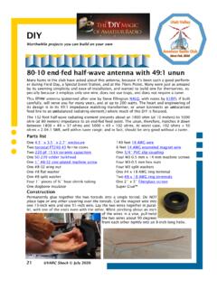
3 Avoiding trap resonance lowers the possibility of trap-voltage breakdown. True resonant-current feed is obtained on the four bands, making the Antenna compatible with either 50 or 75- coaxial-cable feed lines. Fundamental-frequency operation is provided on 80 and 40 meters, and long-wire, odd-harmonic operation on 17 and 10 Antenna is a rewarding and inexpensive project for those of you who like to homebrew your own equipment. I designed the Antenna with a little cut and try using my new Trap and Stub Dipole Antennas for Radio Amateurs computer software package. [1]Figure 1 An Improved 80, 40, 17 and 10-meter trap ConstructionTrap construction is relatively easy, even for those with few manual skills and tools.
4 Figure 2 is a photograph of a trap; Figure 3 is the trap schematic. Double-coax-wound traps have two parallel windings of coax cable (A and B) rather than a single-cable winding. The two shield windings and center conductors are each connected in parallel. The series loss resistance of the trap dominated by skin effect is essentially halved by the parallel connection. The surface area for convection and heat conduction away from the trap is essentially doubled. Power losses in the polyethylene dielectric of the trap are almost negligible because of the relatively low frequencies involved.
5 July QST: An Improved Multiband Trap Dipole Antenna - Page 1 arrl 1996 QST/QEX/NCJ CD Ci ht (C) 1997 b Th AiR di R lLI Figure 2 Close-up of a completed trap. Figure 3 Double-coax trap SWR performance of the Antenna at my location, using a 50 to 75- transformer and a 75- feed line, is shown in Figure 4. The Antenna is installed as an inverted V with a 40-foot apex height. Notice the very good performance on 40 meters, where the SWR is less than 2 across the entire band. The Antenna favors the low end of 10 meters, where most of the activity seems to be concentrated.
6 On 17 meters, the SWR is close to 3 across the band, requiring an Antenna tuner to keep the rig happy. The 2:1 SWR bandwidth on 80 meters is 75 kHz, centered on MHz. A good Antenna tuner can extend the operating bandwidth on 80 meters well into the CW portion of the band or into the General class phone QST: An Improved Multiband Trap Dipole Antenna - Page 2 arrl 1996 QST/QEX/NCJ CD Ci ht (C) 1997 b Th AiR di R lLI Figure 4 SWR plot of the Improved trap measured the Q of these traps at two widely separated low frequencies and extrapolated the results to the higher operating frequencies.
7 This two-frequency extrapolation method solves an otherwise impossible problem of directly measuring the Q of coaxial-cable traps. This approach separates the dielectric losses and the skin-effect ohmic losses of the trap; it assumes the skin-effect losses vary as the square root of frequency, and the dielectric losses vary as the first power of frequency. The results are shown in Figure 5, where the Q of an RG-59 double-coax trap is compared with the Q of a common RG-59 coax trap. The Q of a common RG-58 coax trap is also shown. The superiority of the double-coax configuration is clearly evident.
8 The superiority of RG-59 over RG-58 is also demonstrated. All traps are tuned to a nominal MHz and are of the optimum Q and length/diameter ratio. As you can see, the double-coax RG-59 configuration has a Q about 18% higher than the common singly wound coax configuration. Figure 5 Trap quality factor, Q, versus calculated the trap losses for the bands covered using Roy (W7EL) Lewallen s EZNEC program. The results are shown in July QST: An Improved Multiband Trap Dipole Antenna - Page 3 arrl 1996 QST/QEX/NCJ CD Ci ht (C) 1997 b Th AiR di R lLI Table 1.
9 The Antenna was assumed to be horizontally mounted, 40 feet above real ground and using the legal power-output limit of 1500 W PEP. The stray capacitance of the outer shields of the coax traps was simulated as a length of #14 wire hanging down from the outboard end of the traps. The ratio of PEP to average power is assumed to be 2:1, corresponding to ideal two-tone single-sideband modulation. Notice the very high radiation efficiency and negligible trap dissipation on 40, 17 and 10 meters. On 80 meters, however, the Antenna s low height and its shortened length reduce the Antenna input resistance to , making trap loss significant.
10 On 80 meters, the trap Q is 171. The combined loss from both traps equals dB on this band, an insignificant amount. The input-resistance component chargeable to trap loss becomes significant to the extent of dissipating of the input power in the traps as heat. At this power level, there is an average dissipation of W in each trap. The voltage drop across the traps is 2984 V, below the 3400-V rating of the cable. Table 1 Trap Loss SummaryBand (meters)Freq (MHz)Radiation Efficiency (%)Trap Loss (dB)Trap Power Dissipation (W)80 operating experience indicates that common coaxial-cable traps can dissipate 35 W or more without failure.