Transcription of 8500 and 9000 Replacement instructions for Awning Fabric ...
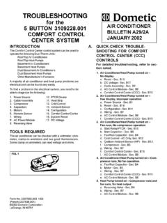
1 1B. REMOVAL OF THE Awning FROM THE COACHFIG. 11/2" TEKSCREWAWNINGRAILREMOVE FROMBOTH SIDESFABRICSECTIONTOPBRACKETS crewdriverElectric DrillStep Ladder3/16" PopRivetsPop RivetVise Grips Socket Wrench Set3/16" Drill Bit1/8" Pop RivetsEnd Cap GuideTools Required:FabricRoller TubeFor Models 8500 & 9000 torsion AssemblyREPLACEMENT instructions FOR AWNINGThe Fabric Roller Tube Assembly (FRTA) consists of a Fabric ,a roller tube and torsion extreme care. Springs under tension aredangerous. If not controlled they will unwindquickly. Keep hands and clothing clear of topcasting, as personal injury may GENERAL INSTRUCTIONS4. Remove both of the patio feet from their mountingbrackets and extend the adjustable arms until each patiofoot rests on the ground and lock button locks in a Slide the Awning Fabric or roller cover out of the To keep the awnings from unwinding during thisstep, be sure the cam lock lever is in the roll downposition. A 1/8" cotter pin can be inserted in eachtorsion assembly for positive locking of the rollertube.
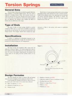
2 See FIG. : Awning removal from the coach is NOT necessarywhen replacing a torsion assembly. Proceed to SectionC, Steps 1 & 2, Sections D, Steps 1-3, and Section L,Steps In all instances of Fabric or roller tube Replacement , it willbe necessary to have a large work area to allowcomplete unrolling of the Awning . This work area mustbe clean and smooth so the Fabric will not be Remove the TEK screws securing the Awning Fabric orroller cover at each end of the Awning Fabric . See FIG. Remove both top mounting brackets on the ends of theawning rail. See FIG. 1 REVISIONForm No. 3/02(Replaces )(French ) 2002 Dometic CorporationLaGrange, IN 46761 These instructions must be read and under-stood before installation, adjustment, serviceor maintenance is performed. This unit mustbe installed by a qualified serviceman. Modi-fication of this product can be extremely haz-ardous and could result in personal injury orproperty CASTINGCOTTERPINMOVE LEVER POSITION TOROLL DOWN POSITIONRIGHT-HAND SIDE(VIEWED FROM FRONT)FIG.
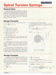
3 2 ToolAdjustable Wrench1/8" Drill BitSmall File2C. UNWINDING A torsion ASSEMBLY SPRINGNOTE: If the Awning is installed on a coach, complete thefollowing steps on a step ladder, with the Awning fabricunrolled two feet from the Awning rail. The unwinding can alsobe done while standing on the ground and the Awning fullyextended and the opposite side rafter locked in place. Thetorsion spring will be wound with 8/eight more turns in thisposition and is extremely injuries can result from the rapid spin-off ofthe top casting. Use Vise Grips - NEVER use barehands - to handle a top casting under spring Clamp a Vise Grip tightly on the top casting, or insertthe crank ( ) into top casting. Remove the 1/4-20 hex head machine screw from the top casting. SeeFIG. 3 and FIG. Take the top casting carefully out of the main supportarm (see NOTE below). Slowly let the torsion springunwind completely. Repeat Steps 1 & 2 for the : If the Awning 's right-hand torsion assembly has beenpinned, the cotter pin must be removed from the torsionassembly before the spring can be unwound.
4 The cam locklever on the right-hand torsion assembly must be turnedclockwise to the roll up position, before the spring can Make sure the torsion spring has been relieved of itstension (see Section C.)2. Mark or make note of the location of the Fabric and theend cap on the roller tube. This is necessary to repositionthe new torsion , Fabric or roller tube exactly the samewhen the new part is : Some roller tubes have notches and the end caphas tabs, that will allow the torsion to fit only in oneposition. The Fabric must be positioned exactly as shownin FIG. 5 or the lock lever will not be positioned correctlywhen installed on the Drill out the two rivets using a 3/16" drill bit. Removetorsion assembly and rivet bodies from roller tube. SeeFIG. HOW TO REMOVE A torsion ASSEMBLYLOCKLEVERTOPCASTINGMAIN SUPPORTARM ASSEMBLYVISE-GRIPS 1/4-20 X 1/2" HEXHD. MACH. SET SCREWFIG. 3 FIG. 4 FIG. 3 ALOCKLEVERTOPCASTING1/4-20 X 1/2" HEXHD. MACH.
5 SET SCREWMAIN SUPPORTARM HOW TO REMOVE Fabric FROM ROLLER TUBE / COVER1. Remove both torsions. See Section D, Steps 1-3 fortorsion Roll the Awning completely out on a clean With the Awning laying flat, slide the roller tube out The metal roller cover on 8500 and 9000 models areF. INSTALLING Fabric ON ROLLER TUBE1. Unfold the new Fabric and lay it on top of the existingfabric in the exact same position. Be sure the newfabric is the correct size and color. If roller tube is beingreplaced, make sure it is the correct length and positionit with the notch located as shown in FIG. Dometic requires the use of the end cap guide to preventdamages to the Fabric , when replacing the Fabric /rollertube. Place the end cap guide supplied with the replace-ment Fabric /roller tube on the end of the roller tube. Slidethe Fabric and valance ropes through the end cap guideand onto the roller tube. See figure : When changing the Fabric , it is vital that the samegroove(s) be used.
6 This eliminates the need to redrill anyholes ( center support).3. Guide the roller tube over the poly-rope(s) of the careful not to damage the roller tube or the to the poly ropes. Use needle nose pliers andflat blade screw dirver to spread open the channel beforeremoving : Some 9000 model Awning ,secured the Fabric to theroller cover with 1/8" pop rivets. It is necessary to removethe 1/8" pop rivets from both ends of the roller the rivets are removed, you can slide the Fabric outof the cover. See FIG. 6 & 5 ROLLERTUBESLIDE Fabric ANDVALANCE ROPESTHROUGH GUIDE4. Center the Fabric on the roller tube and hand-roll the entireassembly in the same direction as the original ENDCAP GUIDEON ROLLERTUBE4 Installing a new Replacement Fabric on 9000 Modelawning roller cover with 6 slats. See FIG. Follow steps 2-8 in Section Fabric Replacement ON 9000 WITH 6 SLAT ROLLER COVERG. Fabric Replacement ON 9000 WITH 7 SLAT ROLLER COVERI nstalling a new Replacement Fabric on a Model 9000roller cover with 7 slats and a vinyl strip.
7 See FIG. 6:1. Remove vinyl strip A (FIG. 11), and hinge slat B (FIG. 10)from top slat C (FIG. 8). Remove two of Slat D (Fig. 9).Discard vinyl strip A, hinge slat B and the two D slats .2. Remove top slat C (FIG. 8) from roller cover assemblyand keep to be installed : 9000 Awning with 6 slats requires removal of oneslat D. ( 8500 and 9000 with 5 slats will require one slatD to be remove and discarded if a new roller cover is beingreplaced.)3. The new Replacement Fabric will be installed as shown inFIG. Use a small file to round the ends of the groove in the5/16" channel of the main slat D (FIG. 9).5. Slide the 5/16" channel of the main slat D onto the poly-Installing a new Replacement Fabric on 8500 and 9000model Awning roller cover with 5 slats. Use Section Follow steps 2-8 in Section Fabric Replacement ON 8500 AND 9000 WITH 5 SLAT ROLLER COVER rope located approximately 12" from the top edge of Install two pop rivets in the main slat D on both ends toprevent the Fabric from shifting in roller cover.
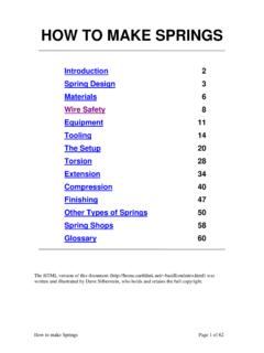
8 If a newroller cover assembly is being installed, a 1/8" hole willneed to be drilled 1-1/2" to 2" from end of the main slatfor the pop rivets. To prevent damage, be sure to removeany burrs left by the : On 8500 models crimp the channel with pliers tohold Use a small file to round the ends of the 5/16" grooves onthe top slat C (FIG. 8) to prevent tearing of the the top slat C onto both the 1/4" channel of the fifthmain slat D and the poly-rope 1-1/2" from the edge of Install the screws into the edge of the roller coverassembly. See FIG. new roller cover on model 9000 with 6 FIG. Follow steps 1-8 in Section INSTALLING NEW ROLLER COVER WITH 6 SLATSK. INSTALLING NEW ROLLER COVER WITH 5 SLATSI nstalling new roller cover on 8500 model with 5 slats .See FIG. Follow steps 1-8 in Section " CHANNELTOP SLAT "C"VIEW RH ENDMAIN SLAT "D"VIEW RH ENDHINGE SLAT "B"INSTALL A 1/8"POP RIVETEACH ENDDDDDDCINSTALL A 1/8"POP RIVETEACH ENDDDDDDCVINYL STRIP "A"EHINGE SLAT "B"FIG.
9 6 FIG. 7E5/16" CHANNELINSTALL TOWARDCANOPYFIG. 10 FIG. 9 FIG. 8 FIG. 11 VINYL STRIP "A"FOR FIGS. 6 11A - VINYL STRIPB - HINGE SLATC - TOP SLATD - MAIN SLATE - Awning RAILFIGURES 6 THROUGH 115/16" CHANNELBOTH ENDS1/4" CHANNELINSTALL TOWARDAWNING RAIL5/16" ROD INAWNING RAIL3/8" CHANNELFOR VINYLSTRIP "A"Note:FIG. 6 shows 9000 model with 7 slats (1 "B" hinge slat, 1 "C" top slat and 5"D" slats).FIG. 7 shows 9000 Model with 6 slats (1 "C" and 5 "D" slats).Drill out 1/8" poprivet, beforesliding out fabricDrill out 1/8" poprivet, or spreadcrimp beforesliding out fabricTrim poly ropeeven and crimpendTrim poly ropeeven and crimpend6 NOTE: If the roller tube is new, the rivet holes are not torsion assemblies must be positioned as follows:The left-hand torsion assembly position has the openslot in the end cap aligned with the empty groove of theroller the right-hand torsion assembly open holein the end cap in alignment with the empty groove in theroller a new right-hand torsion assembly is beinginstalled and the roller tube does not have the notchshown in FIG.
10 5. The two tabs inside the right-handtorsion end cap must be broken off. See FIG. : Placing the end caps as suggested usuallypositions the lock lever in the proper position whenawning is closed. The Awning should be opened andclosed several times, and checked. The cam lock levershould be at the "11:00" position . The end cap may haveto be removed and repositioned if it is not in the properlocation. See FIG. 8500 and 9000 19' - 25' have been manufac-tured with both standard and heavy duty torsionsprings. Before reinstalling the torsion , properlyidentify (Standard or Heavy Duty) the springs. Thisis necessary for proper winding of the torsion . SeeSpring Identification Chart on page Secure torsion assemblies to roller using 3/16" dia. x 3/8"long stainless steel pop To reduce the possibility of the poly rope interfering withthe cam lock mechanism, the right-hand torsion requiresthe valance rope to be cut off even with the roller Steel Roller Tube: The poly rope on the Fabric sidemust be pulled toward the valance groove and cutoff leaving enough length to tuck it behind thevalance groove.