Transcription of 9c- Geometric Dimensioning & Tolerancing (Part 3)
1 Geometric Dimensioning & Tolerancing ( part 3)KCEC 1101 Introduction to GDT basic Geometric Dimensioning and Tolerancing (GDT) was developed over the last forty years as a tool to define parts and features more efficiently. GDT takes the function of the part into consideration, as well as its fit with related parts. This allows the designer to define the parts features more accurately, without increasing the on GDT Within the last 15 years there has been considerable interest in GDT, in part because of the increased popularity of statistical process control.
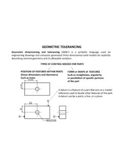
2 This control process, when combined with GDT, helps reduce or eliminate inspection of features on the manufactured object. The flip side is that the part must be toleranced very efficiently; this is where GDT comes in. Another reason for the increased popularity of GDT is the rise of worldwide standards, such as ISO 9000, which require universally understood and accepted methods of of GDT symbols At the heart of GDT is a rectangular box, called the feature control frame, in which the Tolerancing information is FEATURE OF SIZE This rule covers the individual feature size and states.
3 Where only a tolerance of size is specified, the limits of size of an individual feature prescribe the extent to which variations in its Geometric form, as well as size, are allowed. The critical point is that GDT is concerned with both the shapeand positionof feature of size If a shaft consider to mount liner positioning bearings which are used for sliding rather than rotation motion. In this case, the shaft must be highly accurate in size and roundness, but that same accuracy is not possible for the straightness.
4 This situation is common in machine control design. Maximum material condition (MMC) is the condition in which: An externalfeature, like a shaft, is its largestallowable size. An internalfeature, like a hole, is its smallestallowable size. Taken together, it means the part will weigh its maximum. Three symbols pertaining to material conditionsare: M= Maximum material condition L= Least material condition. This is the opposite of MMC (the part will weigh its minimum) S= Regardless of material size. This indicates the material condition is not to be considered.
5 The envelope principledescribes an idealized MMC of a part . Since any departure from MMC means less material, all parts should fit within an envelope described by MMC. One of the keys to is that it allows separation of size from form. This added flexibility means that part can be manufactured at the highest allowable tolerance (and thus lowest cost) and still work. This two variables can be manipulated to meet the particular demands of the part functionalityInspection tools There are several inspection tools used in industry, and their use is important to the science of Tolerancing .
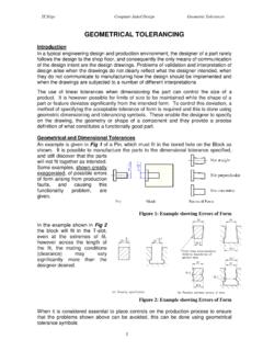
6 Surface plate Height Gage Caliper Micrometer Precision spindle Centers Dial indicator Coordinate measuring machine (CMM)Surface plateHeight gageCaliperMicrometerDial indicatorCMMDATUMS AND DATUM FEATURES A datumis a starting point for a dimension. Datums are theoretically ideal locations in space such as a plane, centerline, or point. A datum may be represented either directly or indirectly by an inspection AND DATUM FEATURES The surface of the object which is placed on the inspection device representing the datum is called the datum feature.
7 These datum features are clearly marked in the drawings to indicate which are the reference surfaces to make measurements Uses Once a datum is established, the measurements can be taken from it rather than features on the object. That is to say, the object feature representing the datum is aligned/placed on the inspection device and the measurement is taken. The datum establishes the method of locating other features on the object relative to each Uses This figure shows the difference in measuring fro a surface plate (datum) versus from the part itselfDatums and assembly Datumsare not only used internal to a part but, more importantly, in relation to mating parts in an reference frame Datums are the locators and the datum reference frameis the six degrees of freedom of movement from the datum.
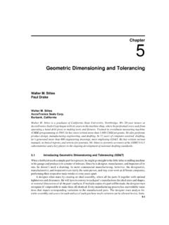
8 The six degrees of freedom are the plus and minus directions along the three Cartesian coordinate axes. Move up, down, left, right, forward & backward. Another way of looking at the frame is as three orthogonal planes. Two-plane datum reference frame in which the hole is dimensioned from the left and bottom Three-plane datum reference planePrimary datum At a minimum, a part will have a primary datum. This datum will be chosen based on a number of criteria: Stability. This is the most important feature. Often dictating that the largest, flattest surface is chosen.
9 Functional relationship. How does the feature mate/interact with other features? Accessibility. Can the part be mounted and measured on the inspection device via this feature? Repeatability. Variations in the datum feature due to manufacturing should be predictable so they can be accounted datums Secondary and tertiary datums, if needed, should be located mutually perpendicular to each other and to the primary control Geometric controlsfall into three major categories: Form controls Orientation controls Position controlsForm controls Form controlsare a comparison of an actual feature to a theoretically perfect one.
10 The controls include: Straightness Roundness, flatness CylindricityForm control: Straightness Straightness. All form controls are variations and combinations of straightness. Straightness itself is based on a line element. Straightness has two distinct variations: Line element straightness. Axis straightness. Line element straightness. This compares a line on the part to a perfectly straight line. If the line is on a flat surface, the direction must be control: StraightnessForm control: Straightness Axis straightness.