Transcription of Geometric Dimensioning and Tolerancing - NEMES
1 DOA's GDT Page!Page 1 of 15 ~dalea/ Dimensioning and Tolerancing 2000, Dale O. Anderson, The views and opinions expressed in this article are those of the author and DO NOT represent the official position of Louisiana Tech University or the State of Louisiana. Waiver of Author's LiabilityThe author, Dale O. Anderson, , provides the information in this article "as is" and makes no warranty, either express or implied, concerning its accuracy or fitness for use in any particular situation. The author's sole intent in providing this information is to enhance the educational experience of his engineering students and to stimulate their thought processes. Anyone choosing to use this information does so at their own risk. The author recommends that any design procedure or data be carefully examined by a potential user to determine if it is both accurate and appropriate for use in each potential application. IntroductionGeometric Dimensioning and Tolerancing (GDT) is a uniform method of stating and interpreting engineering design requirements listed on a shop drawing.
2 It replaces the traditional dimension with attached tolerance ( inch) previously used on engineering drawings. The basis of GDT is the American standard ANSI Adherence to standards facilitates the exchange of data within an organization and between organizations. There is less likelihood of misinterpretation. GDT is closely based on the actual measurement techniques (metrology) used to check the tolerance. Therefore, all tolerances are related to specific properties of a particular feature. A dimensional tolerance is, or should be, related to the variance of the measurement, which includes variations in locating the part on the machine tool, positioning variations in the machining process, variations in the tool, and metrology variations in the inspection process. The most common practice in engineering design is to assign tolerances by "rule of thumb" based on experience with a particular machining process. However, the recommended practice is to assign "six sigma" tolerances (plus or minus three standard deviations) to basic dimensions based on the expected variance in the machining process [Bowker, 1972, Table of Contents:Introduction, Dimensioning , Datums, Feature Control Frame, Position Tolerancing , Linear Feature Tolerancing , Circular/Cylindrical Feature Tolerancing , Profile FeatureTolerancing, Misc.]
3 Feature Tolerancing , Tolerance Stacking, General Guidelines, Glossary, References, Links, end, DOA's GDT Page!Page 2 of 15 ~dalea/ 86-87]. If statistical process control techniques are being used on the machining process, sufficient historical data should be available to produce a good estimate of the variance of the process. Six sigma tolerances lead to three failures (out of tolerance parts) in every thousand parts on average..go back to the table of DimensioningThe basic mechanics of adding dimensions to a drawing have not changed with the advent of GDT. What has changed is the way the dimension value is specified. In GDT, a dimension value is enclosed in a box WITHOUT the tolerances attached. Tolerances are added in feature control frames. Table 1. Confidence (Reliability) Levels for Dimensional TolerancesTolerance/ Standard DeviationSymmetricAsymmetricComments00%0 % experimental confidence level -- 5 failures per "six sigma" tolerances -- 3 failures per failure per failure per millionNOTE: the total confidence of an asymmetric tolerance is the sum of the upper and lower confidences.
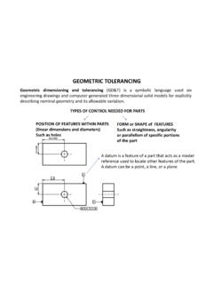
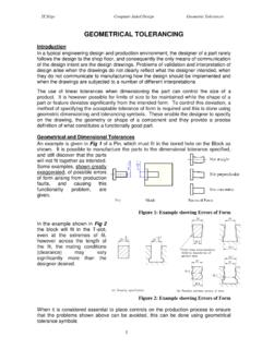
4 Table 2. GDT Dimensioning SymbologySymbolDescriptionThis is a basic (exact) linear dimension. Notice the box around the value. Tolerances are added to a basic dimension by a feature control frame. This is a basic (exact) diameter. The symbol denotes diameter. Tolerances are added to a basic diameter by a feature control frame. This is a basic (exact) radius. The symbol R denotes radius. Tolerances are added to a basic radius by a feature control frame. DOA's GDT Page!Page 3 of 15 ~dalea/ ..go back to the table of DatumsA datum is a reference surface, plane, line or point used to facilitate the definition of features on a part. A datum is normally a locating surface to be used for measurement. For flat features, the locating surface should be a flat, machined surface on one of the outside boundaries of the part. For round features, the locating surface should be an exterior cylindrical surface. Normally for a part with flat surfaces, three mutually perpendicular reference planes are defined for the part (see figure 1).
5 The intersections of those reference planes form the traditional three-axis coordinate system -- a rectangular (Cartesian) coordinate system. The primary datum plane or locating surface is defined by three reference points (because three points define a plane). The secondary datum plane or locating surface is defined by two additional points (because only two points are necessary to define a plane perpendicular to the primary locating plane). The tertiary datum plane or locating surface is defined by a single additional point (because only one point is required to define a plane perpendicular to both the primary and secondary planes). Figure 1. A Cartesian Coordinate System Defined by Reference is an OLD STYLE (nonGDT) linear dimension with symmetric bilateral tolerances applied. The first number is the basic dimension and the second number is the tolerance applied to the basic dimension. The tolerance specification allows the dimension to vary from to + is an OLD STYLE (nonGDT) linear dimension with asymmetric bilateral tolerances applied.
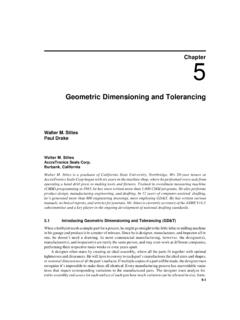
6 The first number is the basic dimension, the second number is the positive tolerance applied to the basic dimension, and the third number is the negative tolerance. The tolerance specification allows the dimension to vary from to + is an OLD STYLE (nonGDT) linear dimension with a unilateral tolerance applied. The first number is the basic dimension, the second number is the positive tolerance applied to the basic dimension, and the third number is the negative tolerance. The tolerance specification allows the dimension to vary from to DOA's GDT Page!Page 4 of 15 ~dalea/ back to the table of Feature Control Frame - TolerancesA feature control frame (see figure 2 below) is a standard way to specify tolerances for specific features on a part. Figure 2. A Generic Feature Control FrameThe symbols listed in the following table MUST be attached to a feature symbol to become tolerances. Table 3. GDT Datum SymbologySymbolDescriptionA datum identification symbol -- a reference surface, line, point or feature labeled A.
7 The referenced feature must actually exist on the part and be accessible for measurement. A datum line or axis defined between points A and B. A datum target symbol for point #1 on datum A. Table 4. GDT Feature Control Frame SymbologySymbolDescriptionThis is a symmetric feature tolerance that denotes the size of the tolerance zone about the basic dimension ( ). The tolerance zone for a single datum is a line segment. The tolerance zone for two perpendicular datums is a circle. The tolerance zone for three perpendicular datums is a sphere. The units must be specified on the drawing. This is an asymmetric feature tolerance that denotes the size of the tolerance zone about the basic dimension (+ , ). The tolerance zone for a single datum is a line segment. The tolerance zone for two perpendicular datums is a rectangular box. The tolerance zone for three perpendicular datums is a right rectangular prism. The units must be specified on the drawing. This is a symmetric diameter tolerance ( ).
8 The units must be specified on the drawing. This is a symmetric radius tolerance ( ). The units must be specified on the drawing. A tolerance modifier that denotes "most material condition." This modifier indicates a feature that contains the maximum amount of material ( minimum hole diameter & maximum shaft diameter). DOA's GDT Page!Page 5 of 15 ~dalea/ ..go back to the table of Position Tolerancing ..go back to the table of Linear Feature TolerancingA tolerance modifier that denotes "least material condition." This modifier indicates a feature that contains the minimum amount of material ( maximum hole diameter & minimum shaft diameter). A tolerance modifier that denotes "regardless of feature size." The tolerance is applied to the feature dimension only and does not include any size information. This is the preferred modifier for statistical process control. A tolerance modifier that denotes "projected tolerance." Table 5. Position Tolerance SymbologySymbolDescriptionMetrologyThis is a position target to which a linear measurement tolerance zone is applied.
9 For one datum, the tolerance zone is a line segment. For two perpendicular datum lines or surfaces, the tolerance zone is a circle (symmetric tolerance) or an ellipse (asymmetric tolerance). For three perpendicular datum surfaces, the tolerance zone is a sphere (symmetric tolerance) or an oblate spheroid (asymmetric tolerance)This measurement may be made by hand or on a linear coordinate measurement system. Table 6. Typical "Best" (Minimum) Tolerances for Various Positioning Operations (Rao, 1992, p. 191)ToleranceRelativeMachining OperationinchesmmCostFlame Cutting (by hand) 1/8 ( ) (by hand on a drill press) 1/16 ( ) Milling & Turning Milling & Turning Milling & Turning Welding (by hand) 's GDT Page!Page 6 of 15 ~dalea/ features are the easiest to machine and to measure. Table 7. Linear Feature Tolerance SymbologySymbolDescriptionMetrologyA linearity or straightness tolerance. The tolerance zone is a rectangular area centered along the specified line and bounded by two parallel lines.
10 This is a 1-D measurement in which a dial indicator may be moved along the line in question. The tolerance refers to the total indicator surface flatness tolerance. The tolerance zone is a rectangular prismatic volume aligned along the specified surface and bounded by two planes. This is a 2-D measurement that may be checked by locating the part on the surface in question and then moving a dial indicator over the entire surface. The tolerance refers to the total indicator parallelism tolerance with respect to a datum line or surface. The tolerance zone is a rectangular area or volume aligned along the line or surface feature and bounded by two parallel lines or tolerance can be measured by locating the part on datum surface and then moving a dial indicator along the line or across the surface. The tolerance refers to the total indicator perpendicularity tolerance with respect to a datum line or surface. The tolerance zone is a rectangular area or volume aligned along the perpendicular line or surface and bounded by two parallel lines or planes.