Transcription of A FERRITE ROD LOOP FOR VLF - TPG Internet
1 1 of 4A FERRITE ROD LOOP FOR VLF by Lloyd Butler VK5BR(Originally published in "Amateur Radio", November 1990 )IntroductionIn a previous article (reference 1), I made comparisons between the performance at MHz of the FERRITE rod loop aerial and openframe loop aerials. Experiments were carried out using a FERRITE rod 20cm long by diameter and open loops square. Generally speaking, the open loop aerials performed with signal sensitivity considerably better than the FERRITE loop aerial. However, at frequencies below 100 kHz, I was able to achieve results which were essentially the winding 1540 turns on the FERRITE rod in several pies, an inductance of more than 100 millineries was obtained with the low distributed capacitance of around 50 pF.
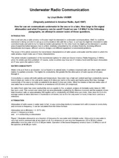
2 Using a 15 to 450 pF x 2 gang variable capacitor and a switchable 100 pF fixed capacitor, a tuning range of 11 to 52 kHz was achieved. Higher frequency tuning was made possible by tapping down to junctions between the pies. The large number of turns used at the low frequencies provided a considerable advantage and, below 100 kHz, the signal sensitivity was found to be as much as 10 dB better than an open loop aerial with which it was detail on the FERRITE rod loop aerial and the comparison open loop is given in the paragraphs which of the LoopsThe FERRITE rod was over wound with two pies of 600 turns and one each of 240 turns and 100 turns as shown in figure 1.
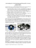
3 The pies were wound in a criss-cross pattern to reduce capacitance between individual turns,and this formed a winding shape similar to that shown in the diagram. Machine-wound honeycomb-formed pies would have been better had one of these machines been 1 Layout of FERRITE Loop Aerial WindingsThe diagram (figure 2) shows the loop switching and tuning circuit and its connection via the interface amplifier. Combined with the twoparalleled sections of the tuning gang capacitor, the series connection of all pie windings is tunable between and 52 kHz. Tuning is extended down further to 11 kHz by switching in a 1000-pF capacitor across the circuit. Higher frequencies are tuned by switching out one or more of the pies.
4 Q factor of the FERRITE loop measured reasonably high at the lower frequencies. At 20 kHz it was of 4 Figure 2 FERRITE Loop SwitchingTuning and Interface Amplifier3 of 4 The amplifier is the same as that previously described for VLF-LF loops (reference 2) except that the two resistors at the amplifier input have been increased in value to one megohm. This was necessary because of the higher value of inductance in the FERRITE loop aerial, the consequent higher parallel impedance at resonance and the necessity to make the amplifier input resistance high by comparison so that it does not greatly lower the circuit open loop aerial, used for comparison, was made up of 20 turns of wire spaced laterally apart by 1cm on a square frame.
5 A similar 20-turn loop aerial was described in reference 2, but the shielded wire in this was replaced by a heavier gauge of unshielded wirewith diameter conductor. Without shielding, self resonance was increased to 750 kHz as compared to 100 kHz achieved with the shielded wire. This allowed tuning the full range of 10 to 500 kHz without tapping down loop turns. Of course, with only 500 microhenriesof inductance, this loop had been tuned with large values of capacitance switched in as described in reference 2. The heavier gauge wire also increased the Q factor which measured 20 at 20 ShieldingOne thing that is very noticeable about the FERRITE loop aerial at these low frequencies is its high sensitivity to noise pickup from nearbymains cables.
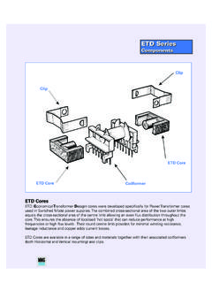
6 This is possibly aggravated by the higher impedance of the loop circuit which makes it more sensitive to electrostatic pick-up. Those who have had audio frequency experience with high impedance valve grid circuits, working at low levels, will recognise the need for shielding from the mains leads and other stray noise. The lower VLF extends into the upper audio range and, similarly, electrostatic shielding of the high impedance FERRITE loop circuit, including tuning components, is also essential. The loop aerial itself requires a special form of shield which does not act as a short circuit around the loop, restricting magnetic induction into its windings.
7 Figure 3 is a sketch of an open-ended aluminium box which was built as a shield around the aerial under discussion. Observe that one edge of its lid is electrically isolated from the side of the box by insulating 3 FERRITE Loop Aerial ShieldEven with shielding, the FERRITE loop still picks up some noise, and I found it necessary to operate the aerial at least one metre away fromany power of PerformanceSignal sensitivity (or the ratio of output volts to field strength in volts per metre) for the 20-turn open loop was calculated from the loopformula to be a value of at 20 kHz. Signal sensitivity for the FERRITE loop was difficult to determine from calculation.
8 Two of the variables in the formula are the corrected permeability and the area (and hence the diameter) of the turns. With the method of winding used, the value of corrected permeability was not clearly defined, and the diameter of turns varied from one centimetre at the centre of a pi to cm at the outside. However, using some averaging and a little guesswork, it appeared that, with all windings in circuit, the ferriteloop should be at least equal to, or more sensitive than, the 20-turn open loop. In practice, this proved to be correct, and, at VLF, the FERRITE loop was found to have a sensitivity advantage. At 43 kHz, the two loops had much the same sensitivity.
9 At Omega frequencies (around 12 kHz) the FERRITE loop produced a signal level about 10 dB greater than the open the FERRITE loop is quite sensitive at VLF and the lower part of the LF spectrum, its sensitivity falls off as turns are tapped down to enable tuning to higher frequencies. In fact, with only the 100 turn pi in circuit to tune up to 500 kHz, I had great difficulty in detecting the 4 of 4strongest of NDB stations. In consequence, the 100-turn junction was not connected into the loop switching circuit, which is shown in figure from its higher sensitivity at VLF, the FERRITE loop has an advantage over the open frame loop in size and portability.
10 On the other hand, the open loop is less prone to pickup of localised noise, and I have found that, even if less sensitive, it gives a better signal-to-noise ratio in the presence of such using appropriate windings as discussed, the FERRITE rod loop aerial can be made to operate with high signal sensitivity in the VLFspectrum. Furthermore, the values of self inductance and capacitance are such that the loop can be tuned over the VLF range of frequencies with an ordinary receiver variable tuning gang the sample FERRITE loop aerial has been found to be more sensitive at VLF than a typical open frame loop aerial, it is inclined to pick up more noise, and its good performance is not maintained above 100 concluding this third article on receiving loop aerials, I must add that these aerials are an interesting field of experimentation which can be carried out with simple materials and minimal cost.