Transcription of A HIGH EFFICIENCY CHARGE PUMP FOR LOW VOLTAGE …
1 International Journal of VLSI design & Communication Systems (VLSICS) , , June 2012. A high EFFICIENCY CHARGE PUMP FOR. LOW VOLTAGE DEVICES. Aamna Anil1 and Ravi Kumar Sharma2. 1. Department of Electronics and Communication Engineering Lovely Professional University, Jalandhar, Punjab, India 2. Department of Electronics and Communication Engineering Lovely Professional University, Jalandhar, Punjab, India ABSTRACT. A CHARGE pump is a kind of DC to DC converter that uses capacitor as energy storage elements to create a higher or lower VOLTAGE power source. CHARGE pumps make use of switching devices for controlling the connection of VOLTAGE to the capacitor. CHARGE pumps have been used in the nonvolatile memories, such as EEPROM and Flash memories, for the programming of the floating-gate devices. They can also be used in the low-supply- VOLTAGE switched-capacitor systems that require high VOLTAGE to drive the analog switched.
2 This paper includes VOLTAGE analysis of different CHARGE pumps . On the basis of VOLTAGE analysis a new CHARGE pump is proposed. 1. INTRODUCTION. A CHARGE pump circuit provides a VOLTAGE that is higher than the VOLTAGE of the power supply or a VOLTAGE of reverse polarity. In many applications such as Power IC, continuous time filters, and EEPROM, voltages higher than the power supplies are frequently required. Increased VOLTAGE levels are obtained in a CHARGE pump as a result of transferring charges to a capacitive load and do not involve amplifiers or transformers. For that reason a CHARGE pump is a device of choice in semiconductor technology where normal range of operating voltages is limited. CHARGE pumps usually operate at high frequency level in order to increase their output power within a reasonable size of total capacitance used for CHARGE transfer.
3 This operating frequency may be adjusted by compensating for changes in the power requirements and saving the energy delivered to the CHARGE pump. Among many approaches to the CHARGE pump design, the switched-capacitor circuits such as Dickson CHARGE pump are very popular, because they can be implemented on the same chip together with other components of an integrated system. The VOLTAGE gain of Dickson CHARGE pump is proportional to the number of stages in the pump. It may cost quite many devices and silicon area, when a CHARGE pump with the VOLTAGE gain larger than 10 or 20 is needed. Such high VOLTAGE gains are required for low VOLTAGE EEPROMs, and typically more than three stages of Dickson CHARGE pump are used. Improved Dickson CHARGE pumps for low VOLTAGE EEPROMs and flash memories are developed. CHARGE pump operates by switching ON and OFF a large number of MOS switches which CHARGE and discharge a large number of capacitances, transferring energy to the output load.
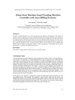
4 Large DOI : 43. International Journal of VLSI design & Communication Systems (VLSICS) , , June 2012. amount of energy is lost whenever the load current is reduced. Savings of switching energy were primary reason for the design efforts, where a special circuit organization was proposed to regulate switching frequency whenever a requirement for the load current changes. There is a need for better understanding of the design tradeoffs related to CHARGE pump design. 2. LITERATURE REVIEW. The first widely used VOLTAGE boosting circuit was the Cockcroft-Walton VOLTAGE multiplier [1]. This circuit, shown in Figure , uses diodes and serially connected capacitors and can boost to several times the supply VOLTAGE . The Cockcroft-Walton CHARGE pump provides efficient multiplication only if the coupling capacitors are much larger than the stray capacitance in the circuit, making it undesirable for use in integrated circuits.
5 Figure 1: Cockcroft-Walton CHARGE pump The Dickson CHARGE pump [2] circuit is presented as an improvement of Cockcroft-Walton circuit. In the Cockcroft-Walton CHARGE pump circuit, the coupling capacitors are connected in series. This results in higher output impedance as the number of stages increases. In[2] the Dickson CHARGE pump circuit, the coupling capacitors are connected in parallel and must be able to withstand the full output VOLTAGE . This results in lower output impedance as the number of stages increases. Both circuits require the same number of diodes and capacitors and can be shown to be equivalent. The drawback of the Dickson CHARGE pump circuit is that the boosting ratio is 3 degraded by the threshold drops across the diodes. The body effect makes this problem even worse at higher voltages. In [3], A novel mixed-structure CHARGE pump based upon the combination of the modified CTS.
6 CHARGE pump and cross-coupled output stage to reduce the output threshold-drop by the output MOS-diode transistor in the smart VOLTAGE controller based CTS CHARGE pump. An enhanced modified-CTS CHARGE pump structure which combines the modified-CTS CHARGE pump with a simplified cross-coupled output stage. A feedback CHARGE pump circuit that uses cross-coupled NMOS switches are used to achieve a high boost ratio for a low- VOLTAGE DRAM word-line driver. This circit uses two capacitors that are switched in such a way that during every clock cycle, one capacitor is charged to the supply VOLTAGE and the other capacitor is boosted to twice the supply VOLTAGE by the clock. The two capacitors reverse roles every clock cycle, causing the VOLTAGE at the output to be a square wave that switches between VDD and 2 VDD. Two of these cross-coupled NMOS pairs are used along with another type of CHARGE pump and an inverter to make up the complete boosted VOLTAGE generator.
7 An earlier circuit that switches between 4 two networks of capacitors is described in [4] as an inductance-less dc-dc converter. A lot of work has been done in recent years involving CHARGE pumps for use in DRAM circuits. In, a high - EFFICIENCY word-line driver for a DRAM is presented. In [5], a CHARGE pump circuit that provides a negative substrate bias for a DRAM is presented. 44. International Journal of VLSI design & Communication Systems (VLSICS) , , June 2012. In, the cross-coupled NMOS CHARGE pump introduced in [6] is used to improve the speed of a pipeline A/D converter by boosting the clock drive in order to reduce the on-resistance of transmission gates in the pipeline. This work also utilizes a bias VOLTAGE generator to bias the n- well to twice the supply VOLTAGE , preventing latch up from occurring during the initial startup transient. CHARGE pumps are also widely used in the program circuits and word line drivers in an EEPROM.
8 A CHARGE pump for use in low- VOLTAGE EEPROM's is presented. This circuit is similar to the Dickson CHARGE pump, but it uses a bootstrapped clock generator to eliminate the threshold drops across the pass transistors. A different method for eliminating the threshold drops in the Dickson CHARGE pump is presented in . 3. DICKSON CHARGE PUMP. John F Dickson proposed a VOLTAGE multiplier circuit. The MOST's in Dickson CHARGE pump function as diodes, so that the charges can be pushed only in one direction. However the nodes of the diode chain are coupled to the inputs via capacitors in parallel, instead of series so that the capacitors have to withstand the full VOLTAGE developed along the chain. Two pumping clocks are used. The two pumping clocks Clk1 and Clk2 are out of phase and have a VOLTAGE amplitude V. The value of is equal to VDD. Through the coupling capacitors C1-C4, two clocks push the CHARGE VOLTAGE upward through the transistors.
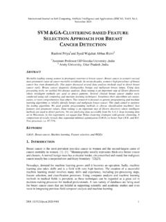
9 Cs is the parasitic capacitance assosiated with each pumping node, f is the frequency of the pumping clocks and is the output current loading. The Dickson CHARGE pump circuit shown in Figure 2 has been widely deployed for generating higher voltages. This circuit consists of capacitor stages connected by diodes and coupled in parallel by two non-overlapping clocks. The diode-connected NMOS transistors are used instead of p-n junction diodes for implementing the circuit in standard CMOS process. The diode- connected NMOS allow the CHARGE flow only in the direction of the output stage in ideal conditions. The charges are pushed from one stage to the next, resulting in higher DC VOLTAGE at the output. Figure 2: A Four Stage Dickson CHARGE Pump When Clk1 goes from low to high and Clk2 goes from high to low, the VOLTAGE at node 1 is settled to and the VOLTAGE at node 2 is settled to , where and are defined as steady-state lower volatge at node 1 and node 2.
10 Both MD1 and MD2 are reverse biased and the 45. International Journal of VLSI design & Communication Systems (VLSICS) , , June 2012. charges are being pushed from node 1 to node 2 through MD2. The final VOLTAGE difference between node 1 and node 2 is the threshold VOLTAGE MD2. The necessary condition for the CHARGE pump to function is that must be larger than the MOST's threshold VOLTAGE , . The VOLTAGE pumping gain for the second pumping stage is defined as the VOLTAGE difference between and . The drawback of Dickson CHARGE pump is that the boosting ratio is 3 degraded by the threshold drop across the diodes. The body effect makes this problem even worst at high voltages. 4. CHARGE PUMP USING STATIC CTS'S. Static CTS CHARGE pumps are new CHARGE pumps employing dynamic switches to increase the VOLTAGE pumping gain The basic idea behind these multipliers is to use MOS switches with precise on/off characteristics to direct CHARGE flow during pumping rather than using diodes, or diode connected transistors which inevitably introduce a forward VOLTAGE drop at each node.