Transcription of A METHOD FOR GENERATING ELECTRICITY BY …
1 A METHOD for GENERATING ELECTRICITY by Fast Moving Vehicles , , and M. Manoj Kumar2 1 Angel College of Engineering & Technology/ECE, Tirupur, India Email: 2 Angel College of Engineering & Technology/ECE, Tirupur, India Email: { , Abstract A METHOD for GENERATING ELECTRICITY using high wind pressure generated by fast moving vehicles channelling the induced wind in the direction of the wind turbine; converting the energy of the wind into mechanical energy by using wind turbine; and converting the mechanical energy into electrical energy by using a GENERATING device and can be used for applications. Keywords: Renewable Energy, Wind, Wind Turbines, etc. I. INTRODUCTION In this modern age more and more energy is required for daily consumption in all walk of life.}
2 Sources and quantum of fossil energy are dwindling day by day and getting exhausted at a very fast rate. Hence conservation, tapping new sources of energy and harnessing of the same from the various non conventional sources, is an important aspect of energy production/conservation and utilization all over the world. The sky-rocketing price of crude oil has ruined the economy of many a country, hence there is a crying need for production of energy from non conventional sources at the earliest. The present concept is one of the answers to this problem, as the said induced wind into useable electric energy which can be utilized straight away or stored in batteries. II.
3 ENERGY REQUIREMENTS World primary energy demand grows by per year on an average between 2006 and 2030 - an increase of 45%. Demand for oil rises from 85 million barrels per day now to 106 mb/d in 2030 - 10 mb/d less than projected last year. Modern renewable energies grow most rapidly, overtaking gas to become the second-largest source of ELECTRICITY soon after 2010. With increasing environmental concern, and approaching limits to fossil fuel consumption, wind power has regained interest as a renewable energy source. This new generation of wind mills produce electric power and are more generally used for all applications, which requires power. III. FIELD OF INVENTION A. Back Ground The fixed wind powered ELECTRICITY generation systems in use, till now are dependent on wind direction and the force of the wind.
4 But the wind is not available at all place and all time through out the year. Therefore, there exists an immense need of a system for GENERATING ELECTRICITY from wind induced by moving vehicles, trains or airplanes, which is available through out the year at various places and with sufficient force of wind. Therefore this invention provides a solution to the problem for GENERATING ELECTRICITY in this manner. B. METHOD This invention relates to a METHOD for GENERATING ELECTRICITY using high wind pressure generated by fast moving vehicles channeling the induced wind in the direction of the wind turbine. A fast moving vehicle compresses the air in the front of it and pushes the air from its sides thereby creating a vacuum at its rear and its sides as it moves forward.
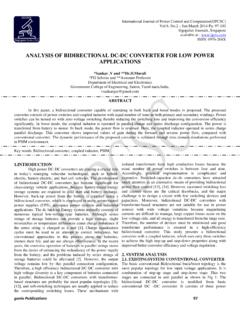
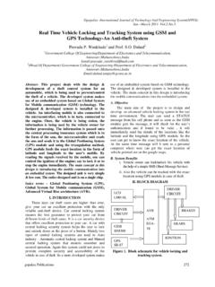
5 Figure 1. Typical Train Model The kinetic energy of the wind movement thus created can be used to generate ELECTRICITY . The moving vehicles encounters wind may be railway trains or airplanes, will sweep off it, in a faster manner making heavy winds. During this, when a wind turbine, if fit to the moving vehicle will generate adequate amount of energy. The air flow will cause turbine to rotate and thus ELECTRICITY can be produced. IV. OBJECTS OF THE INVENTION The main object of the present invention is to provide a METHOD and a system for GENERATING ELECTRICITY using easily available wind induced by moving vehicles/airplanes in transit or in operation. The other object of the invention is to provide a METHOD and a system for GENERATING ELECTRICITY by using high wind pressure generated by moving vehicles, using this free renewable input namely air and independent of the vagaries of seasonal winds having the variation in direction and wind speeds when they do flow and that too neither at all times or places nor having the necessary force of wind to operate wind mill to generate ELECTRICITY as required.
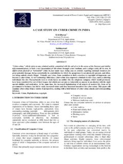
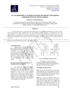
6 V. DESCRIPTION OF INVENTION Figure 2. Basic flow diagram A. Capturing wind induced by moving vehicles The moving vehicles may be all types of light or heavy vehicles running on road, such as two, three, four wheelers or even bigger vehicles. The moving vehicles could be railway train running on railway track. The vehicles could also be aircraft moving on to the runway, taking off or landing; when testing the propellers in the workshops, proceeding to or standing bye in the holding area before taking off. These induces fast winds in all it direction of propagation. B. Routing the induced wind in the direction of the wind turbine If the wind is properly directed towards the wind turbine blades, optimum ELECTRICITY may be generated.
7 The desired direction of wind is obtained by a means for channelling wind, in the direction of the wind turbine. Channeling of wind in a desired direction may be obtained by, at least one truncated cone or pyramid shaped housing or a pair of planar members converging towards the blades of the wind turbine. Aerodynamics is the science and study of the physical laws of the behavior of objects in an air flow and the forces that are produced by air flows. The shape of the aerodynamic profile is decisive for blade performance. Even minor alterations in the shape of the profile can greatly alter the power curve and noise level. Therefore a blade designer does not merely sit down and outline the shape when designing a new blade.
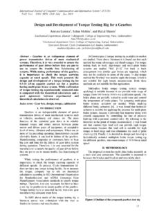
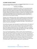
8 Figure 3. Aerodynamics of Wind The aerodynamic profile is formed with a rear side, is much more curved than the front side facing the wind. Two portions of air molecules side by side in the air flow moving towards the profile at point A will separate and pass around the profile and will once again be side by side at point B after passing the profile s trailing edge. As the rear side is more curved than the front side on a wind turbine blade, this means that the air flowing over the rear side has to travel a longer distance from point A to B than the air flowing over the front side. Therefore this air flow over the rear side must have a higher velocity if these two different portions of air shall be reunited at point B.
9 Greater velocity produces a pressure drop on the rear side of the blade, and it is this pressure drop that produces the lift. The highest speed is obtained at the rounded front edge of the blade. The blade is almost sucked forward by the pressure drop resulting from this greater front edge speed. There is also a contribution resulting from a small over-pressure on the front side of the blade. Compared to an idling blade the aerodynamic forces on the blade under operational conditions are very large. Most wind turbine owners have surely noticed these forces during a start-up in good wind conditions. The wind turbine will start to rotate very slowly at first, but as it gathers speed it begins to accelerate faster and faster.
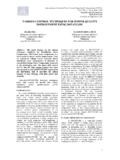
10 The change from slow to fast acceleration is a sign that the blade s aerodynamic shape comes into play, and that the lift greatly increases when the blade meets the head wind of its own fast acceleration, near the wind turbine s operational rotational speed, places great demands on the electrical cut-in system that must capture and engage the wind turbine without releasing excessive peak electrical loads to the grid. Figure 4. Rotation of rotor The desired direction may be transverse or parallel to the direction of plane of rotation of blades depending upon the type of wind turbine used or the direction of wind, or it the design of the wind turbines. The turbines are connected to ELECTRICITY generator to generate ELECTRICITY .