Transcription of A MULTIZONE BUILDING MODEL FOR MATLAB/SIMULINK …
1 Ninth International IBPSA Conference Montr al, Canada August 15-18, 2005. A MULTIZONE BUILDING MODEL FOR MATLAB/SIMULINK ENVIRONMENT. Zaki El Khoury*, Peter Riederer*, Nicolas Couillaud*, Julie Simon**, Marina Raguin**. *Centre Scientifique et Technique du B timent, 84, Avenue Jean Jaur s, 77421 Marne la Vall e Cedex 2, France ** Gaz de France - GDF, 361 Avenue Pr sident Wilson, 93211 Saint Denis la Plaine, France seconds) that is crucial for control purposes, has ABSTRACT modular structure (so it's easy to replace a block or MATLAB/SIMULINK is known in a large number of fields add a new one) and is transparent to the user (an as a powerful and modern simulation tool. In the field expert Simulink user can access internal variables of of BUILDING and HVAC simulation its use is also the MODEL ).
2 This transparency is due to the exclusive increasing. However, it is still believed to be a tool use of Simulink blocks and Matlab language (no S- for small applications due to its graphical structure functions written with C ). and not to fit well for the simulation of MULTIZONE buildings. This paper presents the development of a MATLAB AND SIMULINK. new MULTIZONE BUILDING MODEL for MATLAB/SIMULINK Matlab environment, implemented into the SIMBAD. BUILDING and HVAC Toolbox. It's general enough to Matlab is a high level language dedicated to technical MODEL a variety of useful cases. Conforming to the computing (Matlab, 2004). It is based on matrix Simulink philosophy, the MODEL is modular and operations: the matrix is the basic datatype for structured into blocks to represent the modelled Matlab.
3 Beside its built-in and main functionalities, phenomena. To simplify the description of the Matlab has a wide variety of toolboxes developed for simulated BUILDING , a graphical user interface specialized technologies such as control systems, SIMBDI is developed in parallel, generating an xml neural network and several other domains. BUILDING description file. This file can be read directly Simulink by the SIMBAD MULTIZONE BUILDING MODEL . Finally, a Simulink is a software package for dynamic systems simulation case is presented in order to compare the (Simulink, 2004), used in parallel with Matlab. It can new MODEL with the Trnsys MULTIZONE BUILDING MODEL . MODEL linear and nonlinear systems using continuous INTRODUCTION time, sampled time or a combination of both.
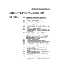
4 Simulink is very suitable for problems that have a The present work is intended to complete the MODEL known configuration. On the other hand, it is more library Simbad BUILDING and HVAC toolbox difficult to deal with general purpose models, such as (SIMBAD, 2003). This toolbox provides ready to use a complete BUILDING MODEL . For example, it is simple HVAC models and related utilities to perform to MODEL with Simulink a time independent state dynamic simulation for buildings and HVAC plants. space problem. It is given by: The development of this toolbox was motivated by the IEA annex 17 concerning virtual laboratories X& = AX + BU (1). (Annex 17, 1993), where several research groups developed principles for the realisation virtual When A and B are time independent matrices, this laboratories (Laitila, 91) and (Va zi, 91).
5 System can be easily modeled with Simulink (cf. To date, Simbad has several BUILDING models that are figure 1). The matrices A and B can either be defined mono-zone models. When the user needs to simulate directly (if known) or calculated in separate Matlab a MULTIZONE BUILDING , he had to break it down to functions or scripts. Simulink will initialise those several monozone blocks and to couple them matrices before the simulation start. manually, that can be a source of mistakes. Therefore, CSTB, in cooperation with GDF, started to develop a MULTIZONE BUILDING MODEL that facilitates the modelling of MULTIZONE buildings. This new MODEL is developed with a graphical interface SIMBDI' to draw the BUILDING and to enter data interactively.
6 Among other features, the Simbad MULTIZONE MODEL allows the use of small timesteps (in the order of Figure 1 A state space problem with Simulink;. - 525 - The bar above a variable indicates a vector (not a The problem is more complicated when these scalar). Aa, Ba,s and Ba,p are matrices that are matrices are time dependent. In this case, the defined by the BUILDING zones. This way of modeller has two possibilities: description is also used in the following sections. 1. Split down the problem to a set of time Walls MODEL independent blocks;. 2. Use the S-function block that allows to Multilayer walls are modelled using constant thermo- use other programming languages such as C physical properties for each layer.)
7 The heat transfer is and Fortran. assumed to be one-dimensional. The wall surfaces For this BUILDING MODEL , we have chosen the first can be of two kinds: those in contact with air and approach. Its implementation is described hereafter. those with imposed surface temperature (called boundary surfaces). MODEL COMPONENTS The governing equations for a wall are thus: A complete description of the mathematical and The heat conduction equation within each layer (j) of numerical treatments is not possible in this paper. So the wall: only a brief description of the assumptions and the Tw 2 Tw mathematical formulation is given for the MODEL = j (8). t x 2. components as well as a general description of the where different modules of the MODEL .
8 Kj j = (9). Air zones MODEL j Cp j Each air zone is assumed to be homogeneous in The boundaries conditions are: temperature. Every zone has two set points: one for cooling and one for heating. The zone air temperature If the first surface of the wall is on contact can vary between these two set points. with air: When the air temperature is allowed to fluctuate T. (inbetween the two setpoints), the zone heat balance k1 w = hc,1 (Ta ,1 Tw x =0 ) + 1 (10). is used to predict the air temperature variation: x x =0. a V Cp a T&a , z = Pw,c + Peq,c + Pg ,c + Pv + Pcpl (2) If it has an imposed temperature: where Tw x =0. = Tb,1 (t ) (11). Pw,c = hc,i Ai (Ts ,i Ta , z ) (3) If the second surface of the wall is on i contact with air: Pv = m& v ,i Cp a (Tv ,i Ta , z ) (4) T.
9 Kn w = hc,2 (Ta ,2 Tw x = L ) + 2 (12). i x x = L. Pcpl = m& cpl ,i Cp a (Ta ,az ,i Ta , z ) (5). i If it has an imposed temperature: In the case where the air temperature tends to be Tw = Tb,2 (t ) (13). outside both set points, the heat balance is used to x =L. calculate the heating or the cooling loads related to the corresponding set point: For each interface between two layers ( j and j+1): T T. kj w = k j +1 w (14). P = Pw,c + Pg ,c + Pv + Pcpl (6) x x = x j x x = x +j To be used into the MULTIZONE MODEL , the above This set of partial differential equations has been equations must be defined in a matricial format (for discretisized using a combined finite difference and all zones of the BUILDING ).
10 For example, the final finite volume schemes. The discretization step for format of the equation (2), used in the MODEL is (now each layer is calculated by: equivalent to equation (1)): x 2j = j t (15). &. Ta = Aa Ta + Ba,s Ts + Ba, p ( Peq,c + Pg ,c + Pcpl + Pv ) (7). The resulting final differential equation for all walls in matrix form is given by: - 526 - Infrared heat exchange &. Tw = Aw Tw + Bw,a Ta + B w, (16) The infrared heat exchange MODEL is based on the assumption that all surfaces behave as black bodies. The black body equation has been linearised. This is where is a vector that contains absorbed incident justified by relatively small differences between fluxes (IR and solar radiation) on the walls surfaces: surface temperatures in buildings.