Transcription of A Performance Monitoring Tool to Quantify Valve Stiction ...
1 A Performance Monitoring tool to Quantify Valve Stiction in control loops R. Bacci di Capaci, C. Scali Chemical Process control Laboratory (CPCLab), Department of Civil and Industrial Engineering (DICI), University of Pisa, Via Diotisalvi n. 2, 56126, Pisa (Italy), e-mail: Abstract: The paper presents main features of a Performance Monitoring system, which allows Stiction quantification. It implements a methodology which permits one to reproduce the unknown stem position, without requiring any additional knowledge, based only on data normally registered in industrial plants (controller output OP, controlled variable PV and set point SP). A general procedure is proposed to discard data for which quantification is very likely to give wrong indications and to restrict the application to appropriate cases.
2 Simulations show that several sources of perturbations can be eliminated; on the contrary, the presence of external disturbances may alter the reliability of Stiction evaluation and then Stiction diagnosis techniques must be applied firstly. Results are confirmed by application to industrial valves for repeated acquisitions, in the framework of a Performance Monitoring system implemented for continuous supervision of control loops and Valve maintenance scheduling and checking. Keywords: Process control Applications, Performance Monitoring , Valve Diagnostics, Stiction Detection, Stiction Quantification 1. INTRODUCTION control loop Performance assessment has been recognized as an important factor to improve profitability of industrial plants.
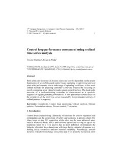
3 In the last years many techniques have been proposed to allow Performance evaluation from routine recorded data and several software packages appeared on the market and are now used as Monitoring tools. A control loop Performance Monitoring system should be able to detect poor performing loops and to indicate different causes, then suggesting appropriate moves to apply on the plant. Main distinction is among external perturbations, controller tuning and Valve problems: for this reason, techniques able to characterize different sources have been proposed. Certainly Valve Stiction (static friction) is one of the most common causes of Performance degradation (Jelali and Huang, 2010). In Figure 1, the 4 main variables of a control loop are indicated.
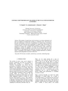
4 Set Point (SP), Controlled Variable (PV) and Controller Output (OP) are usually recorded, while Valve stem position (MV) is not available in general. Fig. 1. The reference scheme for a control loop. The knowledge of MV would allow an easier detection of the presence of Stiction because the linear relationship MV(OP) in a Valve without Stiction , changes to a parallelogram shape in the presence of Stiction (see Figure 2). Fig. 2. MV(OP) plots: left): non-sticky Valve ; right): sticky Valve . When the plant is equipped with Valve positioners and advanced communication systems (as Field Bus), the task is even easier: not only Stiction can be detected, but also other causes of malfunction can be indicated (for instance: air leakage, I/P converter troubles, etc.
5 ; details can be found in Scali et al. (2011), Bacci di Capaci et al. (2013). On the contrary, when MV is not available, the presence of Stiction has to be diagnosed by referring to PV, OP and SP. A detailed illustration and a Performance comparison of the most recent techniques of Stiction detection, on a large benchmark (93 loops ) of industrial data, is reported in Jelali and Huang (2010). As conclusions, this problem can be considered almost solved, even though it cannot be expected that different Stiction diagnosis techniques give always the same results once applied on industrial data. Preprints of the 19th World CongressThe International Federation of Automatic ControlCape Town, South Africa. August 24-29, 2014 Copyright 2014 IFAC6710 On the contrary, Stiction quantification must be considered still an open issue (Jelali and Huang, 2010).
6 The knowledge of the value of Stiction is very important in order to follow its evolution in time, to compare with acceptable thresholds and to schedule and check Valve maintenance. In addition to techniques, as Choudhury et al. (2006), which give an estimate of apparent Stiction , methodologies which Quantify the parameters of a data-driven Stiction model and predict MV signal are much more effective: Srinivasan et al. (2005), Choudhury et al. (2008), Jelali (2008), Karra and Karim (2009), Romano and Garcia (2011), Farenzena and Trierweiler (2012). The main difficulty of Stiction quantification is that the true value of Stiction is not known in industrial data (it may be known in ad hoc experiments or in simulations); therefore, the validation of a proposed technique on a single set of industrial data can be incomplete.
7 This is confirmed by the fact that different quantification techniques can strongly disagree when applied on the same benchmark of industrial data ( in Jelali and Huang, 2010). Therefore, the reliability of Stiction detection and quantification techniques is still under exploration, as showed by Qi and Huang (2011) and Srinivasan et al. (2012). The possibility of diagnosing Stiction is included in several systems of closed loop Performance Monitoring (CLPM), proposed nowadays by major software houses. To the best of the authors knowledge, no commercial tool performs Stiction quantification, object of this contribution. The paper is organized as follows: in Section 2 the proposed method for Stiction quantification is illustrated, while the presence of disturbances is investigated in Section 3; Section 4 illustrates the new tool of Performance Monitoring and Stiction quantification; Section 5 presents results for some industrial loops ; conclusions and further work are reported in Section 6.
8 2. THE PROPOSED METHOLOGY In the proposed Stiction quantification technique, the control loop is modeled by a Hammerstein system (Figure 3, top). About Stiction modeling, a comprehensive activity has been performed by Choudhury et al. (2005), Kano et al. (2004) and He et al. (2007), who developed data driven models, preferred for their simplicity to more accurate physical models (Karnopp, 1985). Kano model is adopted to describe the non-linear Valve dynamics and an ARX (AutoRegressive model with eXternal input) model describes the linear Valve and the process dynamics. The relation between the controller output (desired Valve position) OP and the real Valve position MV is described in three phases (Figure 3, bottom): 1.
9 Block: MV is steady and the Valve does not move, owing to static friction force (deadband + stickband, S). 2. Jump: MV changes abruptly because the active force unblocks the Valve , J. 3. Motion: MV changes gradually, only dynamic friction force can possibly oppose the active force acting on the Valve diaphragm; the Valve stops again when the force generated by control action decreases under Stiction force. Fig. 3. Top): Hammerstein system; bottom): Valve Stiction modelling. Valve Stiction produces an offset between PV and SP and causes loop oscillation because the Valve is stuck even though the integral action of the controller acts and increases the pressure. In case of Flow control loop, the fast dynamics allows one to approximate MV(OP) with PV(OP) plot.
10 It is worth saying that the value of J is critical to originate limit cycles (Choudhury et al., 2008), but, while S is easy recognizable, it is hard to detect J in industrial data, owing to its small value and the presence of field noise (Figure 2, right). The proposed Stiction quantification technique is based on a grid search (see Figure 4), method which is simple and mathematically robust. Even though computation times can be longer with respect to other techniques, that does not represent a limitation, as the technique requires data registered for hours, the phenomena of wearing in valves occur slowly (weeks or months) and the valves maintenance usually occurs periodically (on the occasion of plant shutdown).