Transcription of A UHF+ Bridge - W1GHZ.org
1 A UHF+ VSWR Bridge Being able to measure VSWR at UHF and microwave fteguencies can aid those homebrew projects H ams frequently need to mea- sure VSWR. This is para- mount for antennas, as it is the only parameter conveniently mea- sured, but it is also useful in rnany homebrew projects. Most of the VSWR meters we use for antennas are based on directional cou- plers and require a significant amount of power for a useful reading. Many electronic devices are intolerant of that much power, and sometimes the frequency involved is outside the ham bands where it is undesirable as well as illegal to use transmitter power levels. A simple resistive VSWR Bridge can give good results over a wide fre- quency range with milliwatts of power. I found a nice surplus unit for the 2 to 12-GHz range which works so By Paul Wade, N1 BWT well that I wanted one for lower fre- quencies.
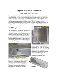
2 I saw WlAIM using a Bridge to trim the phasing harness for his EME array, and he reminded me that Joe Reisert, WlJR, had described one some years ago.' I later visited Joe at Antennaco and saw the origlnal unit still being used to test antennas. The WlJR unit is easily built in a small aluminum box and works up to about 450 MHz. He pointed out that the technique could be extended to several GHz-just what I was looking for. I decided to build one as small as I could using inexpensive chip resis- tors and capacitors that are now com- monly available. The circuit, shown schematically in Fig 1, is quite simple. How it works is more obvious if it is redrawn as a Wheatstone Bridge , Fig 2, with R1 equal to R2 is the reference load 161 Center Road Shirley, MA 01464 'Notes appear on page 5 connected to 52, and R4 is the un- known impedance connected to 53; if they are exactly the same, then the voltage at each end of R5 is the same, so there is no detected output and the VSWRis This condition is referred to as having the Bridge balanced.
3 Any difference between R3 and R4 unbal- ances the Bridge and causes an output from the detector. Detected output is proportional to Bridge imbalance: the higher the VSWR, the greater the out- put. At high frequencies, all components have inductance and capacitance. Since we would like the Bridge to oper- ate at as high a frequency as is possible, it is important to minimize the L and C by making the Bridge as small as practical, and then to keep it balanced by making it symmetrical. The smallest robust box that I could think of was n slice of X-band waveguide. I sketched out the compo- February 1995 3 nent dimensions to see if they would fit-it was too tight for my fingers in WR-90 waveguide. KlLPS had a spare piece of WR-112, the next larger size waveguide, with inner dimensions of inches by inches.
4 The parts are mounted on a small Teflon PC board with the etching pattern shown in Fin 3. Since all the lines are as short " as possible, dimensions are not criti- cal; on the original board, I cut out the pattern using a hobby knife. Note that layout and construction are symmetri- cal so that 52 and 53 are electrically identical and interchangeable. Construction is straightforward. The tinned PC board is trimmed to fit snugly in the waveguide, then the SMA connectors, J1, 52 and 53, are mounted and the center pins soldered to the board to hold it in place. Then the unit is inverted to solder the ground plane side to the inside of the waveguide. After applying plenty of flux, a ring of wire solder is fitted around the perimeter of the board, ready to flow into place as soon as it reaches the melting temperature.
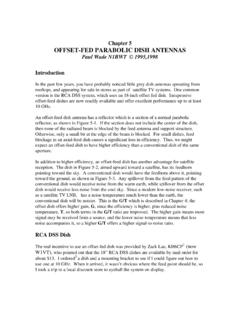
5 The outside of the waveguide is heated with a propane torch applied to the side (right side in Fig 5) that has no SMA connector until the solder melts and joins the PC board to the walls of the waveguide. Don't be timid with the torch-the idea is to get everything hot quickly and remove the heat as soon as the solder flows. If waveguide is not readily avail- able, a suitable enclosure may be fabricated from hobby brass, as de- scribed by The pattern in Fig 3 extends past the waveguide dimen- sions to allow some flexibility in packaging. After the flux is scrubbed off, com- ponents are soldered in place. Compo- nent placement is shown in Fig 4 and the photograph, Fig 5. A small wire passes through the board to the BNC connector and R8 underneath. Operation of the Bridge is also straightforward.
6 A modulated RF sig- nal is applied to J1, and the detected modulation, with amplitude propor- tional to VSWR, appears at 54. Usu- ally the modulation is at 1 kHz, and the detected output is connected to a surplus SWR meter, such as the HP 415. (The solid-state 415D and 415E are more stable than earlier models, but any of them work fine, as do simi- lar instruments from several other manufacturers.) Since the SWR meter is just a tuned audio amplifier with a Input J7 RF J2 R5 J3 51 Unknown Impedance 17'7 J4 Detected Output C3 ;;; 100 k Fig 1-Schematic diagram of the VSWR Bridge . All resistors and capacitors are chip devices except for R8. Dl-Microwave mixer diode. R6, R7-10 to 15 kiL. I h , inch , /A Fig 3-Etching pattern for the printed- circuit board. Use Teflon board and trim Fig 2-The Wheatstone Bridge is the to fit the enclosure (%2 inch recommen- fundamental circuit within the ded thickness).
7 Instrument. calibrated meter, any audio amplifier driving an output meter will do the job. Fig 4-Component placement diagram for the VSWR Bridge . 4 QEX A good 50-R termination is con- nected at 52 as the reference load: the quality of the reference load is impor- tant since all other impedances are compared to it. In fact, we could measure VSWR on a 75-R cable by using a 75-R termination at 52. To calibrate a measurement, con- nect a coaxial short circuit at 53 and adjust the SWR meter scale for infinite VSWR, or 100% power reflected. The unknown impedance is then connected at 53 to measure its VSWR. However, what a typical SWR meter such as the HP415 displays is return loss, the per- centage of reflected power in dB. Most microwave engineers use return loss directly, but if you are more comfort- able with VSWR, this is the equation for conversion (remember that RL is a negative number): RI.
8 1+ 10% SWR = - mr, ~ - Since we have tried to keep the Bridge balanced and symmetrical, a good test is to put good loads on both 52 and 53, then swap them. The mea- sured VSWR should be low (high return loss) and identical in both cases. Now that we've gone to the effort of using chip components and making the VSWR Bridge as small as possible, how much have we gained? With good 50-R SMA terminations at 52 and 53, return loss was greater than 30 dB (VSWR c ) from 10 MHz through 2304 MHz, while at 3456 MHz, the return loss was 22 dB (VSWR = ), so performance is degraded but still usable. However, at 5760 MHz it was worthless. So we have increased the CCI Capacllot K~Icontatns365poeces. bea of even, 10% value lrom lpI10 33~1 CR-1 Res~slor KII conlalns 154 Opleces, lOea olevev 5% valuelrom lOn10 10megll Sizes are 0805 and I206 Each k~t IS ONLY $4995 and ava~lable lor lrnmedlals One Day Dellvev' Order by toll-tree phone.
9 FAX, or mall We accept VISA. MC. COD. or orders Company PO'S accepted w~th approved credll Call lor lree detatled brochure UWMUNMlKWS SKCIALISTS. M 426 Wesl Tall Ave . Orange. CA 9266542% Local (714) 998-3321. FAX (714) Entlre USA 1-800-854-0547 Fig 5-The completed Bridge assembly. upper frequency limit to at least five times as high as the original version. It is possible that this style ofVSWR Bridge could be pushed even higher in frequency by making it even smaller, using tiny (and more expensive) micro- wave chip capacitors and resistors. Notes Parts and boards are available from: DownEast Microwave 954 Rt 519 Frenchtown, NJ 08825 Tel: 908-996-3584 'Reisert, Joe, Wl JR, "Matching Techniques for VHFlUHF Antennas," ham radio, July 1976, pp 50-56. 2 Ryder. John D., Networks, Lines and Fields.
10 Prentice-Hall. 1955. pp 32-37. 3 Healy, Rus. NJ2L, "Building Enclosures for Microwave Circuits," QEX, June 1994, pp 15-17. 00 Optimize your HF operation! Know the best tlrnes and bands for skeds or OX Evaluate statlon changes before maklng them. Wlll e blgger amp do the 1007 What about changlng the snfenne? CAPMAN provldes answers In a user frlendly menu drlven skywave analysis package with context-sensitive help & color graphics. SCP 1994 L~.~II 10. TM nib-. usa m SSM: 37 rl-: rz M: I mmn = .IW NU. J ma WISE = WY. NO. smt = m: mtr ~cvr m un na~nt fa zr8~. F-y 8 Local D-mllmt 111- .. a + + + + + .. ' ". :In I. *--, --- -,,-A U I 1U 1X 14 Ib 1U dU ad d4 u-.* . Ur--lwI~h hm I ,I- YIl~.btlIl~ .. s-1-cc ~mrrrtrc by -r. ulnd bu ~~ttrr or CUB to 11, sm. 1a3 n-11a111t <2> n-tr ad-~~rr <.