Transcription of ABB Kent-Taylor - Controls Warehouse
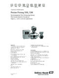
1 AquaProbe Installation Manual Insertion Type Electromagnetic Flowmeters Co nn w ec tio f Flo nI te o nfo Ra rm atio A n te tiva B Ac D. l C. Tota So ck et Des crip A t se tio n 12. V ba Re tte B ry pa ck No. Coi l dr Pinnof ive C ou tput Sign lor al 2. ou tput Tay D. Out nt - pu 2. ts/S. eria Ke WA l in terfa R ce 1. NIN 6. B. AB. G. Do S. 2. ba not m 19. tt Alw ery ake p c 3. un ays ack oil c m re is o En ate pla con nne s d c c dry ure con e pronecte tion be Pro be con nec tec d. s wh fore ne tors tiv ilst ua c e ma tors . ca ps Aq PR tin are on g. cle OD an UC an TC d OD. EN. O. VE. RI. VB BO. DR OW. N. 1 EA. BR. AS. ABB Kent-Taylor ABB Kent-Taylor . The Company BS EN ISO 9001. REG. RM. ABB Kent-Taylor is an established world force in the design and manufacture of FI.
2 ST. I. ERED. instrumentation for industrial process control, flow measurement, gas and liquid St Neots, Cert. No. Q5907. analysis and environmental applications. Stonehouse, Cert. No. FM 21106. As a part of ABB, a world leader in process automation technology, we offer customers application expertise, service and support worldwide. UNI EN 29001 (ISO 9001). We are committed to teamwork, high quality manufacturing, advanced technology and unrivalled service and support. Lenno, Italy Cert. No. 9/90A. The quality, accuracy and performance of the Company's products result from over 100. years experience, combined with a continuous program of innovative design and development to incorporate the latest technology.
3 The NAMAS Calibration Laboratory No. 0255(B) is just one of the ten flow calibration plants operated by the Company, and is indicative of ABB Kent-Taylor 's dedication to quality and accuracy. Stonehouse, Cert. No. 0255. Use of Instructions Warning. Note. An instruction that draws attention to the risk of injury or Clarification of an instruction or additional information. death. Caution. Information. An instruction that draws attention to the risk of damage to Further reference for more detailed information or the product, process or surroundings. technical details. Although Warning hazards are related to personal injury, and Caution hazards are associated with equipment or property damage, it must be understood that operation of damaged equipment could, under certain operational conditions, result in degraded process system performance leading to personal injury or death.
4 Therefore, comply fully with all Warning and Caution notices. Information in this manual is intended only to assist our customers in the efficient operation of our equipment. Use of this manual for any other purpose is specifically prohibited and its contents are not to be reproduced in full or part without prior approval of Technical Communications Department, ABB Kent-Taylor . Licensing, Trademarks and Copyrights MODCELL and PC-30 are trademarks of Asea Brown Boveri, Inc. IBM and IBM PCAT are trademarks of International Business Machines Corp. BantinelPro is a trademark of Rainbow Technologies, Inc. Health and Safety To ensure that our products are safe and without risk to health, the following points must be noted: 1.
5 The relevant sections of these instructions must be read carefully before proceeding. 2. Warning labels on containers and packages must be observed. 3. Installation, operation, maintenance and servicing must only be carried out by suitably trained personnel and in accordance with the information given. 4. Normal safety precautions must be taken to avoid the possibility of an accident occurring when operating in conditions of high pressure and/or temperature. 5. Chemicals must be stored away from heat, protected from temperature extremes and powders kept dry. Normal safe handling procedures must be used. 6. When disposing of chemicals ensure that no two chemicals are mixed. Safety advice concerning the use of the equipment described in this manual or any relevant hazard data sheets (where applicable) may be obtained from the Company address on the back cover, together with servicing and spares information.
6 CONTENTS. Section Page Section Page 1 INTRODUCTION 5 SETTING UP. System Schematic .. 2 Introduction .. 14. Centre Line Method .. 14. Mean Axial Velocity Method (1 8 Diameter) .. 14. 2 PREPARATION Partial Velocity Traverse .. 14. Checking the Code Number .. 2. AquaProbe Transmitter Set-up .. 14. 3 MECHANICAL INSTALLATION. 6 OPERATION. Location Environmental Conditions .. 3. Start-up and Operation .. 15. AquaProbe .. 3. Battery Pack Replacement .. 15. Transmitter .. 3. Location Flow Conditions .. 4. International Standard for Flow 7 FAULT FINDING .. 16. Measurement .. 4. Velocity Limitations .. 5. 8 SPARES. Location Mechanical .. 6. Accessories .. 17. AquaProbe .. 6. Replacement Parts .. 17. Transmitter .. 6.
7 Safety .. 7. Installing the AquaProbe .. 7 APPENDICES. Setting the Insertion Depth .. 8 A1 Testing the Flow Profile for Symmetry .. 18. Centre Line Method for Pipe Diameters Partial Velocity Traverse .. 18. 1m ( 40in) .. 8 Single Entry Point Method .. 18. Centre Line Method for Pipe Diameters Dual Entry Point Method .. 18. >1m to 2m, (>40in to 80in) .. 8 A2 Potting the Probe Head Connections .. 19. Mean Axial Velocity Method .. 9. AquaProbe Alignment .. 9. 4 ELECTRICAL INSTALLATION. AquaProbe Transmitter Socket Identification .. 10. Input and Output Connections .. 10. Data Logger Connections .. 11. Celia Isolated Logger .. 11. Data Logger Configured for Contact Closure .. 11. Bi-directional Data Logger .. 11.
8 Cervelec WS2 Telemetry System .. 11. Grounding .. 11. Cable Type and Preparation .. 12. Probe Head Connections .. 13. Power Supply Unit .. 13. 1. 1 INTRODUCTION 2 PREPARATION. The AquaProbe electromagnetic insertion flowmeter is Checking the Code Number Fig. designed for measurement of the velocity of water. The flowmeter, available in four standard lengths, can be installed in any pipeline of internal diameter from 200mm (8in). to 8000mm (360in), through a small tapping. The AquaProbe has been designed for use in survey applications such as leakage monitoring and network analysis and in permanent locations where cost or space limitations preclude the use of conventional closed pipe meters. System Schematic Fig.
9 Potted Connections Refer to Table Fig. Checking the Code Number Plugs or Sockets (factory fitted). Power Sensor Output Fig. System Schematic AquaProbe Product Code Transmitter Sensor AquaProbe MF/A XXX X 1 0 1 0 X XX 0 AA X 3 0 0 1 0. Length No probe 000. 300mm (12in) 301. 500mm (20in) 501. 700mm (27in) 701. 1000mm (39in) 102. Sliding Joint Not required 0. Connection BSP, with in BSP pressure tapping 1. BSP, with 1 8 in BSP pressure tapping 2. NPT, with 1 8 in NPT pressure tapping 3. 1. Calibration Un-calibrated 8 0. Standard 3 point 1. 8 point 2. Witnessed 8 point 4. Cabling Not fitted or potted 00. 3m 03. 10m Fitted to sensor and potted 10. 30m 30. Power Supply Battery pack 4. Power supply cable 6. Table Code Number Identification 2.
10 3 MECHANICAL INSTALLATION. Location Environmental Conditions AquaProbe Fig. Transmitter Fig. 60 C (140 F) 50 C (120 F). Max. Max. 20 C (-4 F) -20 C (-4 F). Min. Min. A Within Temperature Limits A Within Temperature Limits 10m (30ft). (60in). IP68 (NEMA 6) IP68 (NEMA 6). B Within Environmental Rating B Within Environmental Rating C Avoid Excessive Vibration C Shade from Heat Fig. Environmental Requirements . Fig. Environmental Requirements AquaProbe AquaProbe Transmitter 3. 3 MECHANICAL INSTALLATION. Location Flow Conditions Minimum upstream straight length*. The probe may be installed in one of two positions in the pipe; Type of disturbance upstream from the For a For a either on the centre line or at the mean axial velocity point measuring cross- measurement at measurement on (1 8 pipe diameter).