Transcription of Abutment Sheet Check List - Caltrans
1 BRIDGE design DETAILS AUGUST 1991 ) Abutment Sheet Check List A. Plan 1. Place at top, left side of Sheet , oriented the same as the General Plan. May be placed horizontal with face down for very long abutments. 2. Show North arrow. 3. Scale 1/4" = 1 '-0" usual minimum. Use 1/s" = 1 '-0" on large structures, but show less detail. 4. Abutment Sheet may be omitted on simple diaphragm type abutments. Layout and Sections should be shown with the girder layout. 5. Check List: Do not repeat stations or bearings shown on Foundation Plan. Dimension along same layout line as is stationed on Foundation Plan. Do not dimension piles from edges offootings. Show only layout dimensions and pile spacing, others should be shown on larger details. Avoid showing any reinforcement. B. Abutment Elevation 1. Place in front of Plan if "PLAN'' is oriented the same as a General Plan, "ELEVATION" may be placed horizontal or looking normal to face of Abutment .
2 2. May be omitted on simple diaphragm type abutments. 3. Rear elevations should be avoided. 4. Same scale as Plan 5. Check List: Show location ofweep holes. See Standard Plan B0-3, Bridge Detail3-1. As an alternative, weep holes and geocomposite drain may be used. See Bridge design Details manual page 6-22. Show elevations on slope pavirig; exception, a constant dimension below soffit. Do not attempt to show entire skewed wingwalls. Do not show all piles. Note "All piles not shown." It is not necessary to show railing. Avoid detail dimensions. C. Wingwall Elevation 1. Projection ofAbutment Plan ifpossible. Locate by section symbols ifnot a projection, or simply call out as WINGW ALL ELEVATION. 2. Always show looking normal to wall. 3. Same scale as Plan, unless reinforcement is to be shown. A few bars may be shown at W' = 1'-0", but usually reinforcement should not be shown at less than%"= 1'-0".
3 6-11 BRIDGE design DETAILS AUG 4. Check List: Call out standard plans and wall length. Show fmished earth or slope paving lines. Wingwalllayout dimensions to be shown in Plan view. Show all piles. Railing need not be shown. D. Sections and Details 1. Sections and details showing reinforcement should not be less than Ys" = 1 '-0" scale; preferred scale is ~" = 1 '-0" minimum. 2. Plan of footing comers should be the same orientation as Plan view. 3. Sections should be oriented the same way as the view they are taken from. 4. Sections and details are to be taken from Plan, Elevation, or secondary views rather than from other sections. 5. Similar sections need not have all details repeated. 6. Do not shade or show aggregate in sections. 7. Abutment section call out joint seal and movement rating. E.
4 Retaining Walls 1. Show all layout information along one layout line (usually the face of wall). 2. Do not show dimensions given on standard sheets. 3. Show top of wall details for railings, sidewalks, overhangs, etc. 6-12 BRIDGE design DETAILS JUNE 1990 ) End Diaphragm Abutment ~ ~ ~ \B78" PSP underdrain Pervious and backfill Permeable material Material continuous behind abut. : ..- .: :: ..:: .. :.. , .:.. ::~~ ~ .. :::,a ~.. : :..~-: ..,.. :.:- : ! : .. _; :~ .: -~ .. ~ : ..: .. c;; .. : .. = 0CD ~z ('I) CD ! 5'-0" min. (see Note 4) Notes: 1. Reinforce the Abutment as shown on pages 1-2, 1-3, and 1-4 of the Bridge design Aids .. 2 .. J'he clearan~~_be~~~n~ ~lope and the soffit of ~e J>ri9-g~ ~hould be ab~~t.~~e f~_et, but may .be as little as two feet or as much as four feet, depending upon individual circumstances.
5 This dimension should be shown on the plans. 3. The bottom portion of an end diaphragm Abutment on piles should be embedded a minimum of 3~feet at the intersection of the slope and face of Abutment . 4. For end diaphragm abutments on spread footings, the horizontal clearance from the top offooting to the face of slope should be five feet minimum. 5. Continuous pervious backfill material and drains or perforated pipe with permeable material shall be placed in accordance with the instructions in Memo to Designers 5-2. Note that permeable material is only specified when known water bearing material is present behind the Abutment . 6. Weep Hole and Geocomposite Drains, Bridge design Details 6-22, which is an alternative to Bridge Detail B0-3/3-1, should be added to the plans for abutments without structure approaches. 7. End slopes at abutments shall be 1 ~ to 1 or flatter except under very unusual circumstances.
6 6-21 BRIDGE design DETAILS NOVEMBER 1992 ) Weep Hole and Geocomposite Drain Alternative to Bridge Detail 3-1 Backface of Abutment -- Cap-typ. see Note B Finished or retaining wall grade ,_ 3" Slotted plastic pipe. see Note B Detail "A" Geocomposite Tee connection drain See NoteA See Note B 3. unslotted Detail "B" plastic pipe Wall Section Section A-A Filter fabric Bond to geocompositewrap around drain, 3" min Bond s to wall. Level or slopedCut hole for 3" toward wall pipe. I ' "I 1 0 mil polyethylene Sheet ~'--cementtreated permeable base Detail "A" Detail "B" Notes: A. 4" drains at intermediate sag points and at 25' max. center to center (9' c-c for Type 3 and 9'-3" c-c for Type 4 retaining walls). For walls adjacent to sidewalks or curbs, provide 4" plastic pipe under sidewalk to discharge through curb face. Exposed wall drains shall be located 3" above finished grade.
7 B. Geocomposite drain, cement treated permeable base, and 3" cp slotted plastic pipe continuous behind retaining wall or Abutment . Cap ends of pipe. Provide ''Tee" connection at each 4" cp drain. C. Connect the low end of plastic pipe to the main outlet pipe as applicable. Weep Hole and Geocomposite Drain Page6-22 BRIDGE design DETAILS AUGUST 1981 6-24 STIRRUP. REINFORCEMENT ) AT ABUTMENTS (Sloping Exterior Girder) \.. Inside face of exterior girder at bottom slab -\--- 1 \_Wingwall ACUTE Abutment CORNER r ~'vSome size and spacing asr::;-detailed for girders. See--II_::_ Note I for Sloping Abutments +----+ ' \_Wingwall Inside face of exterior girder( at bottom slab t. Abut OBTUSE Abutment CORNER Notes: I. Additional stirrups or equivalent reinforcing may be required for sloping Abutment face . 2. Consideration should be given to potential conflicts when accomodatino prestressing flares and assemblies.
8 3. These detai Is should be shown in addition to requirements on Standard Plans B6-I and B 7-I BRIDGE design DETAILS MAY 1989 6-25 j BOX GIRDER DIAPHRAGM-SLAB REINFORCEMENT For Skews Greater Than 20 At the junction ofthe bottom slab and end diaphragm ofseat -type abutments, for skews greater than 20 , rebar clearance problems may be encountered. The slab thickness may not be adequate to accommodate the "stacking" oflongitudinal and transverse slab bars, diaphragm stirrups, and diaphragm bottom bars. Possible solutions are shown below. l 1 ~-===> c::::l -== ~ C=> C=> _1_3"min 3"min REINFORCED CONCRETE PRESTRESSED CONCRETE DROP-DIAPHRAGM ALTERNATIVE l 1 Skewed transverse reinforcement -= c:;:::,-=::::) ~c:::;, ::::) c:::;, c:!:::l c:::;) C=> e=> REINFORCED (Shown) -PRESTRESSED (Similar) FLARED SLAB ALTERNATIVE Note: Use in conjunction with page 8-32, Bridge design Details.
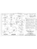
9 " llJ ~ ~~ 1-4 4 -B B or 8--'\,t G? t~J lo'L 11:5II:OII~~ g I. --ILL 1:12' BACK tAlLGIRDER ~kiPS/!1-L---~f=~Mcr-s;..~"-----~~-, kips 0.. 1:122f 28 P8 J2 4026/27/28/29/ JO "" 48 $.. --~~~:=~ -\ .'.J~. 291 ..,J98 492 $07 2611 en' ar .. J61 .,,, .,. ~? 6Jl 1-4 I"" Fal!!!. ~~ .., .-ao~719 lSO a. 2'-0" uud "'' 5JI G)f"" 1ar 467 516 5CI 596 "' 2'..2"add Kips/fl..4 '""f1 ~L - - - __; ron/ 691 102 82 898---------2'-4'" add Kips/It z ~ 60 2 695 751 ..J 2~6"add Kips/fl. ~ ~J ' I ~b. 5'-6" l)sld-for IDCII lO' dtiCriiJSI m "b" add 008 k/fl 0 Not~: Onl WDII ond Slob, raJ/ not mcluded. Slab usmg 1/'-0" g~rdN spacinf. 0 \ ~ ---------~---------I -~ l for tiQc/1 r0 incriJOSiin b" sub/rae/ It/fl. \._--[ I - - --~ FRONT WAU Sf:CTION W W SlOE WALL SPAN I FEET 1:12 Jips/tt kipS ~ AQUTMENT DEAD LOAQ ~ \;-~----_\:_-_.]
10 ::-----=t_-(8\-', 1-4(Span~Girt:Mrrmf srmm . r?rdor t""~\\. t) ,about ~-----------"===~::d\ \~i enGIRDER OEFLF:CTKWS\ \ \ J sl ~j__?l Nolll To/ol dllfiiiCIIfJit Will -' I\ H r KMd DIJ011I 4 WWLOT.::;r-, '----------\ I ~ears t~flt!r false work \.._ 12' 0" I ----_ _:--:__ _} \ removal. For imlal<V-@;-\ 10 Wo/1 dllfllclions oflllr false {~_j TypiCOI ~ j J ' '- " 1=~ :-rM-work riJmoVDI, divitH GIRDER R /NFORCF:MF:NT STIRRIJP SPACING vo/ues shOIINI ~tine. no scale no scale ~ Notos. Add Curb and Ro1llng a! f#(/UirMI. For s1'"tions not shown, su Abulmlnl Dllails" 1h11f. This shill 11/ust,ates how a lypJCOI "Abulm1nf ,wt ..shHI should b1 mad1. Th1 mformalion for gtrdt~r remforcemenl and o lobulation of de(l(/ toads for 20 determlfung numbsr of pills or StZU of spread loofil'gs or1 no/ lo bl placed on /he " Abutment Layout Sheet !))))