Transcription of CHAPTER 9 STEEL PLATE GIRDERS - Caltrans
1 BRIDGE DESIGN PRACTICE FEBRUARY 2015. CHAPTER 9. STEEL PLATE GIRDERS . TABLE OF CONTENTS. introduction .. 1 STRUCTURAL MATERIALS .. 1. Structural STEEL .. 1 Concrete .. 2 SPAN AND FRAMING ARRANGEMENT .. 2. Span Configuration .. 2 Girder 2 Diaphragms and Cross Frames .. 3. Lateral Bracing .. 5. Field Splice Locations .. 5 Expansion Joints and Hinges .. 5 SECTION PROPORTION .. 6 Depth to Span Ratios .. 6 Webs .. 6 Flanges .. 7. Stiffeners .. 8 STRUCTURAL MODELING AND ANALYSIS .. 8 DESIGN LIMIT STATES AND PROCEDURES .. 9 Design Limit States .. 9 Design Procedure .. 9 DESIGN EXAMPLE - THREE-SPAN CONTINUOUS COMPOSITE PLATE . GIRDER BRIDGE .. 11 STEEL Girder Bridge Data .. 11 Design Requirements.
2 12. Select Girder Layout and Sections .. 13 Perform Load and Structural Analysis .. 18 Calculate Live Load Distribution Factors .. 22. Determine Load and Resistance Factors and Load Combinations .. 25. Calculate Factored Moments and Shears Strength Limit 26. CHAPTER 9 - STEEL PLATE GIRDERS 9-i BRIDGE DESIGN PRACTICE FEBRUARY 2015. Calculate Factored Moments and Shears Fatigue Limit States .. 28 Calculate Factored Moments Service Limit State II .. 30 Design Composite Section in Positive Moment Region at Point of Span 2 .. 31. Design Noncomposite Section in Negative Moment Region at Bent 3 .. 45. Design Shear Connectors for Span 2 .. 64 Design Bearing Stiffeners at Bent 3 .. 67 Design Intermediate Cross 70 Design Bolted Field Splices.
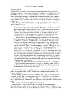
3 77. Calculate Deflection and 98. Identify and Designate STEEL Bridge Members and Components .. 100 NOTATION .. 101 REFERENCES .. 105 CHAPTER 9 - STEEL PLATE GIRDERS 9-ii BRIDGE DESIGN PRACTICE FEBRUARY 2015. CHAPTER 9. STEEL PLATE GIRDERS . introduction . Girder bridges are structurally the simplest and the most commonly used on short to medium span bridges. Figure shows the Central Viaduct in San Francisco. STEEL I-section is the simplest and most effective solid section for resisting bending and shear. In this CHAPTER straight composite STEEL -concrete PLATE girder bridges are discussed. Design considerations for span and framing arrangement, and section proportion are presented. A design example of the three span continuous composite PLATE girder bridge is given to illustrate the design procedure.
4 For a more detailed discussion, reference may be made to texts by Chen and Duan (2014), Baker and Puckett (2013), FHWA (2012), and Taly (2014). Figure Central Viaduct in San Francisco STRUCTURAL MATERIALS. Structural STEEL ASTM A 709 or AASHTO M 270 (Grades 36, 50, 50S, 50W, HPS 50W, HPS. 70W and 100/100W) structural steels are commonly used for bridge structures. CHAPTER 6 provides a more detailed discussion. CHAPTER 9 - STEEL PLATE GIRDERS 9-1. BRIDGE DESIGN PRACTICE FEBRUARY 2015. Concrete Concrete with 28-day compressive strength f c = ksi is commonly used in concrete deck slab construction. Caltrans MTD 10-20 ( Caltrans , 2008) provides concrete deck slab thickness and reinforcement.
5 The transformed area of concrete is used to calculate the composite section properties. For normal weight concrete of f c = ksi, the ratio of the modulus of elasticity of STEEL to that of concrete, n = E/Ec = 8 is recommended by AASHTO (2012). For unshored construction, the modular ratio n is used for transient loads applied to the short-term composite sections, and the modular ratio 3n is used for permanent loads applied to the long-term composite sections. SPAN AND FRAMING ARRANGEMENT. Span Configuration Span configuration plays an important role in the efficient and cost-effective use of STEEL . For cases where pier locations are flexible, designers should optimize the span arrangement.
6 Two-span continuous GIRDERS /beams are not the most efficient system because of high negative moments. Three- and four-span continuous GIRDERS are preferable, but may not always be possible. For multi-span continuous GIRDERS , a good span arrangement is to have the end span lengths approximately 70 to 80. percent of the interior span lengths. Equal interior span arrangements are also relatively economical. A span configuration with uplift due to live load plus impact should be avoided. The use of simply supported GIRDERS under construction load and continuous GIRDERS through STEEL reinforcement for live load can be an economical framing method (Azizinamini, 2007). This type of framing presents possible advantages over continuous beam designs by eliminating costly splices and heavy lifts during girder erection.
7 The potential drawbacks are that more section depth may be required and the weight of STEEL per unit deck area may be higher. This framing method needs to be investigated on a case-by-case basis to determine whether it can be economically advantageous. When simply supported span configurations are used, special attention should be given to seismic performance detailing. Girder Spacing As a general rule, the most economical superstructure design can be achieved using girder spacing within an 11 ft. to 14 ft. range. For spans less than 140 ft., 10 ft. to 12 ft. spacing is preferred. For spans greater than 140 ft., 11 ft. to 14 ft. spacing is recommended. The use of metal deck form panels will limit the spacing to about 16.
8 Ft. Girder spacings over 16 ft. may require a transversely post-tensioned deck system. Parallel girder layout should be used wherever possible. CHAPTER 9 - STEEL PLATE GIRDERS 9-2. BRIDGE DESIGN PRACTICE FEBRUARY 2015. Diaphragms and Cross Frames The terms diaphragm and cross frame are synonymous. Figure shows typical types of diaphragms and cross frames used in I-shaped PLATE girder and rolled beam spans. The K-frames and X-frames usually include a top strut as shown in Figure Intermediate cross frames provide bracing against lateral torsional buckling of compression flanges during erection and deck concrete placement, and for all loading stages in negative flexure regions. They also provide lateral bracing for wind loads.
9 End cross frames or diaphragms at piers and abutments are provided to transmit lateral wind loads and seismic loads to the bearings. Spacing Arbitrary 25 ft. spacing limit for diaphragms and cross frames was specified in the AASHTO Standard Design Specifications (AASHTO, 2002) and the Caltrans Bridge Design Specifications ( Caltrans , 2000). The AASHTO LRFD Bridge Design Specifications (AASHTO, 2012), however, no longer specify a limit on the cross frame spacing, but instead require rational analysis to investigate needs for all stages of assumed construction procedures and the final conditions. Spacing should be compatible with the transverse stiffeners. Figure Typical Diaphragms and Cross Frames CHAPTER 9 - STEEL PLATE GIRDERS 9-3.
10 BRIDGE DESIGN PRACTICE FEBRUARY 2015. Orientation Intermediate cross frames shall be placed parallel to the skew up to a 20o skew and normal to the GIRDERS for a skew angle larger than 20o. On skewed bridges with cross frames placed normal to the GIRDERS , there may be situations where the cross frames are staggered or discontinuous across the width of the bridge. At these discontinuous cross frames, lateral flange bending stresses may be introduced into the girder flanges and should be considered. Install stiffeners on the back side of connection plates if staggered cross frames are used. Horizontally curved GIRDERS should always have the cross frames placed on radial lines. A good economical design will minimize the number of diaphragms with varying geometries.