Transcription of AC Servo Motor and Driver˜ MINAS A4 Series˜
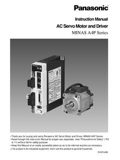
1 Instruction ManualAC Servo Motor and Driver MINAS A4 series Thank you for buying and using Panasonic AC Servo Motor and Driver, MINAS A4 series . Read through this Instruction Manual for proper use, especially read "Precautions forSafety" ( to 11) without fail for safety purpose. Keep this Manual at an easily accessible place so as to be referred anytime as [Before Using the Products]pageSafety 8 Maintenance and 14On Opening the 14 Check of the Driver 14 Check of the Motor 15 Check of the Combination of the Driver and the 16 Parts 26[Preparation]pageSystem Configuration and 28 Overall Wiring (Connecting Example of C-frame, 3-phase).
2 28 Overall Wiring (Connecting Example of E-frame).. 30 Driver and List of Peripheral 32 Wiring of the Main Circuit (A to D-frame).. 34 Wiring of the Main Circuit (E and F-frame).. 35 Wiring to the Connector, CN X6 (Connection to Encoder).. 38 Wiring to the Connector, CN X3 and 4 (Connection to PC, Host Controller or Console).. 40 Wiring to the Connector, CN X5 (Connection to Host Controller).. 41 Timing 42 Built-in Holding 46 Dynamic 48 Caution on 50 Setup of Parameter and 51 Outline of 51 How to Set .. 51 How to 51 Composition and List of 52 Setup of Torque 57 How to Use the Front Panel and 58 Setup with the Front 58 Setup with the 58 Initial Status of the Front Panel Display (7 Segment LED).
3 59 Initial Status of the Console Display (7 Segment LED).. 59 Structure of Each 60 Monitor 63 Parameter Setup 69 Content3 EEPROM Writing 70 Auto-Gain Tuning Function 73 Copying Function (Console Only).. 79[Connection and Setup of Position Control Mode]pageControl Block Diagram of Position Control 82 Wiring to the Connector, CN 83 Wiring Example to the Connector, CN X5 .. 83 Interface 84 Input Signal and Pin No. of the Connector, CN 86 Output Signal and Pin No. of the Connector, CN 92 Connecting Example to Host 96 Trial Run (JOG Run) at Position Control 104 Inspection Before Trial 104 Trial Run by Connecting the Connector, CN X5.
4 104 Real-Time Auto-Gain 106 Applicable 106 How to 106 Adaptive 107 Parameters Which are Automatically 107 Parameter for Functional 108 Parameters for Adjustment of Time Constant of Gains and 111 Parameters for Auto-Gain 112 Parameters for Adjustment (2nd Gain Switching Function).. 115 Parameters for Position 116 Parameters for Velocity/Torque 120 Parameters for 120 [Connection and Setup of Velocity Control Mode]pageControl Block Diagram of Velocity Control Mode ..126 Wiring to the Connector, CN Example to the Connector, CN X5 .. 127 Interface 128 Input Signal and Pin No.
5 Of the Connector, CN 130 Output Signal and Pin No. of the Connector, CN 135 Trial Run (JOG Run) at Velocity Control Mode ..138 Inspection Before Trial 138 Trial Run by Connecting the Connector, CN X5 .. 139 Real-Time Auto-Gain 140 Applicable 140 How to 140 Adaptive 141 Parameters Which are Automatically Set up .. 141 Before Usingthe ProductsPreparationConnection and Setup ofPosition Control ModeConnection and Setup ofVelocity Control ModeConnection and Setup ofTorque Control ModeFull-ClosedControl ModeAdjustmentWhen in TroubleSupplement4 Parameter for Functional 142 Parameters for Adjustment of Time Constant of Gains and 146 Parameters for Auto-Gain 147 Parameters for Adjustment (2nd Gain Switching Function).
6 149 Parameters for Position 151 Parameters for Velocity/Torque 152 Parameters for 155 [Connection and Setup of Torque Control Mode]pageControl Block Diagram of Torque Control Mode .. 160 Wiring to the Connector, CN Example to the Connector, CN X5 .. 161 Interface 162 Input Signal and Pin No. of the Connector, CN 164 Output Signal and Pin No. of the Connector, CN 168 Trial Run (JOG Run) at Torque Control Mode ..171 Inspection Before Trial 171 Trial Run by Connecting the Connector, CN X5 .. 171 Real-Time Auto-Gain 172 Applicable 172 How to 172 Parameters Which are Automatically Set up.
7 173 Parameter for Functional 174 Parameters for Adjustment of Time Constant of Gains and 177 Parameters for Auto-Gain 178 Parameters for Adjustment (2nd Gain Switching Function).. 179 Parameters for Position 181 Parameters for Velocity/Torque 183 Parameters for 185[Full-Closed Control Mode]pageOutline of Full-Closed is Full-Closed Control ?.. 190 Control Block Diagram of Full-Closed Control 191 Wiring to the Connector, CN Example to the Connector, CN X5 .. 192 Interface 193 Input Signal and Pin No. of the Connector, CN 195 Output Signal and Pin No. of the Connector, CN 201 Connection to the Connector, CN 204 Connector, CN X7.
8 204 Wiring to the External Scale, Connector, CN 205 Real-Time Auto-Gain 206 Applicable 206 How to 206 Adaptive 207 Parameters Which are Automatically Set up .. 207 Parameter for Functional 208 Parameters for Adjustment of Time Constant of Gains and 211 Parameters for Auto-Gain 212 Parameters for Adjustment (2nd Gain Switching Function).. 214 Parameters for Position 216 Parameters for Velocity/Torque 220 Parameters for 220 Parameters for 224[Adjustment]pageGain 226 Real-Time Auto-Gain 231 Adaptive Auto-Gain 236 Release of Automatic Gain Adjusting 239 Manual Auto-Gain Tuning (Basic).
9 240 Adjustment in Position Control 241 Adjustment in Velocity Control 241 Adjustment in Torque Control 242 Adjustment in Full-Closed Control 242 Gain Switching 243 Suppression of Machine 246 Automatic Gain Setup Function .. 248 Manual Auto-Gain Tuning (Application)..249 Instantaneous Speed 249 Damping 250 [When in Trouble]pageWhen in Trouble .. 252 What to Check ?.. 252 Protective Function (What is Error Code ?) .. 252 Protective Function (Details of Error Code).. 260 Motor Does Not Run .. 260 Unstable Rotation (Not Smooth)/ Motor Runs Slowly Even with Speed Zero at Velocity Control 261 Positioning Accuracy Is Poor.
10 262 Origin Point 263 Abnormal Noise or 263 Overshoot/Undershoot, Overheating of the Motor ( Motor Burn-Out).. 264 Motor Speed Does Not Reach to the Setup/ Motor Revolution (Travel) Is Too Large or 264 Parameter Returns to Previous 264 Display of "Communication port or driver cannot be detected" Appears on the Screen While using thePANATERM .. 2645 Before Usingthe ProductsPreparationConnection and Setup ofPosition Control ModeConnection and Setup ofVelocity Control ModeConnection and Setup ofTorque Control ModeFull-ClosedControl ModeAdjustmentWhen in TroubleSupplement6 [Supplement]pageAbsolute of the Setup Support Software, PANATERM.