Transcription of MINAS S-series Operating Manual - Panasonic
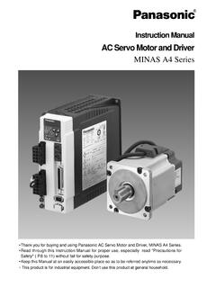
1 AC servo Motor DriverMINAS S-seriesOperating Manual Thank you very much for your buying Panasonic AC servo Motor Driver,A- series . Before use, read through this Manual to ensure proper use. Keep this Manual at an easilyaccessible place so as to be referred anytime as sure give this instruction Manual to the Description 12 Amplifier 12 Motor 13 Installation 14 Amplifier 14 Motor 16 Trial Run 44 Inspections before Trial Run 44 Operation with CN I/F Connected 45 Adjustments 50 Purposes of Gain Adjustments 50 Types of Gain Adjustments 50 How to Adjust Gain 52 How to Use "Normal Auto-Gain" Tuning 53 How to Use "Real TimeAuto-Gain" Tuning 54 How to Adjust Gain Manually 55 Gain Tuning UsingGain Adjustment Rotary Switch 58To reduce the
2 Mechanincalresonance 59 Table of Contents- 2 -Safety Precautions 4 Introduction 8 After Opening the Package 8 Check the Model Number of Amplifier 8 Check the Model Number of Motor 9 Check the Combination of Amplifier and Motor 10 System Configuration and Wiring 18 General Wiring Diagram 18 List of Available Components 20 main Circuits 22CN SIG ConnectorFor Encoder 23CN SER Connector 24CN I/F ConnectorFor Controller 25CN MON Connector 35 Parameter Setting 36 Overview 36 Parameter Groups and Listing 36 Setting the Parameters 41 Overview of PANATERM 41 How to Connect 41 Before UsePreparationsand AdjustmentsTroubleshooting 68 After-Sale Service Back coverDetails of Parameters App.
3 16 Optional Parts App. 38 Recommended Parts App. 47 Dimensions App. 48 Characteristics App. 53 Specifications App. 54 Protective Functions 60 Maintenance andInspections 6 6 Conformance to EC Directives and UL Standards App. 2 Holding Brake App. 6 Dynamic Brake App. 8 Timing Chart App. 10 Acceptable Loads on Output Shaft App. 14 Homing Operation (Precautions) App. 15 AppendixesImportant Information- 3 --4- DANGERS afety PrecautionsObserve the following precautions in order to avoid injuries of opera-tors and other persons, and mechanical damages. The following DANGER and CAUTION symbols are used according to the level of dangers possibly occur-ring if you fail to observe the instructions or precautions indicated.
4 The following symbols indicate what you are not allowed to do, or what youmust observe.(Important)DANGERCAUTIONI ndicates a potentially hazardous situation which, if notavoided, will result in death or serious a potentially hazardous situation which, if not avoided,will result in minor or moderate injury and physical symbol indicates that the operation is symbol indicates that the operation mustbe performed without 't insert your hands inthe to observe thisinstruction could result inburns and/or electric over-current protection, earth leakagebreaker, over-temperature protection andemergency stop should be to observe thisinstruction could result in electricshocks, injuries and/or sure to check safetyafter occurrence of the amplifier securely to pre-vent fire hazard and personal injuryresulting from to observe thisinstruction could result in electricshocks, injuries and/or to observe thisinstruction could result in electricshocks.
5 Injuries and/or DANGERG round the earth terminalof the to observe thisinstruction could result inelectric 't touch the rotatingpart of the motor in to observe this instruction couldresult in partDo not expose the cables tosharp edges, excessivepressing forces, heavyloads or pinching to observe thisinstruction could result inelectric shocks,malfunction the transportation,wiring and inspection atleast 10 minutes after thepower to observe this in-struction could result inelectric 't subject the product towater splash, corrosivegases, flammable gases andcombustible to observe this in-struction could result UseInstall an externalemergency stop device sothat you can shut off thepower in any to observe thisinstruction could result ininjuries, electric shocks, fire,malfunction and/or ask to an electrical engi-neer for PrecautionsUse the motor andamplifier in the to observe this in-struction could result in the trial operationswith the motor fixed butwithout motor load a load to themotor is possible only aftersuccessful trial to observe this in-struction could result in extremeadjustment or an operationwhich causes to observe thisinstruction could result an error occurs,remove the causes forthe error and secure thesafety before restartingthe to observe thisinstruction could result 't touch the motor,amplifier or itsregenerative dischargeresistor, since theybecome to observe thisinstruction could result 't modify, dismantleor repair the to observe this in-struction could result in fire,electric shocks and/or inju-ries.
6 (Important)-7-Caution*Provide appropriate settings as a preparedness againstthe accidental restart of the machine in order to ensurethe safety of equipment should betreated as an industrialwaste when it is disposed 't block the heatdissipation hole or insertforeign matters in to observe thisinstruction could resultin electric shocks,injuries and/or sure that thewirings are to observe thisinstruction could result inelectric shocks, 't hold the cables ormotor shaft whentransporting the to observe thisinstruction could resultin UseAfter recovery from thepower failure, theequipment may restartsuddenly. Don't approachthe equipmentFailure to observe thisinstruction could result the to observe thisinstruction could result inelectric shocks,injuries and/or not turn on/off themain power to observe thisinstruction could resultin ~35~611~12478910 IntroductionAfter Opening the Package Make sure that the product is what you have ordered.
7 Check whether the product has been damaged or not during the Model of AmplifierName plateModel DesignationSeries symbolS: S-seriesRated motor output (seeTable 1-a)If the product is not correct, or it has been damaged, contact dealer or sales 32V 2500P/R1 3 30W50/60Hz 0~ OUTPUT ENCODERAC servo DRIVER60/75 Wire OnlyUse Copper Conductors OnlyRefer to Manual for Wiring and Wire SizeRefer to Manual for Over Load input voltageRated motor outputNumber of pulses of theencoder(resolution)Rated output currentSerial NumberCustomspecificationCustom specification 2(A, B, )A: StandardCustom specification 1 (1,2, )1: StandardRotary encoder (see Table 1-b)Power supply1: Single-phase, 100V2: Single-phase, 200V3: Three-phase, 200V5: Three-phase/Single-phase, 200V (common phase)SymbolMUDA pplicable motorsMUM iExtra low inertia j-9-StraightABCDOil sealNoneYesBrakeNoneYesNoneYesKey wayEFGH1~35~611~12478910 Check the Model of MotorName plateTypeSerial NoRevolution ratingModel DesignationRated output (see Table 1-a)Motor structure(see Table 1-c)AC servo MOTORRATINGS1 Model CLASS B (T V) A (UL)CONT.
8 OUTPUTRATED 3 AC92IP65 VMatsushitaElectric Industrial in JapanRated outputSeries symbolS: S-seriesVoltage1: 100V2: 200VZ: 100/200 VRotary encoder (see Table 1-b)Custom specification 11: StandardCustom specification 2 SymbolMUMTypeSuper low inertiaSymbolATypeIncrementalNo. of pulses2500P/rLead wire11-wireSpecificationsResolution10000 Before UseSymbol3A5A01 Rated output30W50W100 WSymbol020408 Rated output200W400W750 WTable 1-aRated Motor OutputTable 1-bRotary EncoderMotor StructureTable 1-cShaft Specifications with the shaftprovided with key way are the Combination of Amplifier and MotorThe amplifier has been designed for use in combination with the specified motors the specifications ( series symbol, output rating, voltage rating and encoder type) ofthe motor you want to UseWith the incremental type encoder: 2500P/rMotorAmplifiertypeType1 Type2 Type3 Type2 Type3 Type1 Type2 Type3 SeriessymbolMUMSS uperLow inertiaVoltage100V200 VOutputrating30W50W100W200W400W200W400W3 0W50W100W200W400W750 WRevolutionrating3000r/minEncoder typeIncremental2500P/r, 11wiresAmplifierMUDS3A1A1 AMUDS5A1A1 AMUDS011A1 AMUDS021A1 AMUDS041A1 AMUDS022A1 AMUDS042A1 AMUDS3A5A1 AMUDS5A5A1 AMUDS015A1 AMUDS023A1 AMUDS043A1 AMUDS083A1 AMotor typeMUMS3AZ**MUMS5AZ**MUMS011A**MUMS021A **MUMS041A**MUMS022A**MUMS042A**MUMS3 AZA**MUMS5 AZA**MUMS012A**MUMS022A**MUMS042A**MUMS0 82A**Powersupply foramplifier1-phase,100V1-phase,200V3-ph ase/1-phase,200V3-phase,200V-12-Parts DescriptionAmplifier<Notes>For detailed information for each of motor types, see the drawings in the Appendix( to 52).
9 Example: MUDS023A1A(3-phase, 200V 200W: Type 1)Example: MUDS042A1A(1-phase, 200V 400W: Type 3)Rotary switch for gain (GAIN)tuningCommunicationconnector CN SERC ontroller connection (CN I/F)Encoder connection (CN SIG)Check pins (CN MON)Check pins (CN MON)Alarm code LEDS tatus LEDMain power input connector (L1, L2, L3,P, B)EarthconnectionsMotor connection (U, V, W, E)MONCNMSDSMOTORCNSIGCNCNPOWERCNI/FALM CODESTATUSGAINCN SERMOTORSIGPOWERI/FCNCNCNCNMONCNCN SERGAINMSDSALM CODESTATUS-13-<Notes>For detailed information for each of motor types, see the drawings in the Appendix( & 49).MotorExample: Super Low-Inertia Motor (MUMS series , 400W)Mounting bolt holes (4)FlangeFrameMotor cableEncoderEncoder cableBefore UseBrake cable(Motor with electromag-netic brake only )-14-InstallationThe amplifier and motor should be properly installed to avoid failures, mechanical damages and Indoors, where the amplifier is not subjected to rain water and direct sun beams.
10 Notethat the amplifier is not a waterproof structure. Avoid the place where the amplifier is subjected to corrosive gases, flammable gases,grinding liquids, oil mists, iron powders and cutting particles. Place in a well-ventilated, and humid- and dust-free space. Place in a vibration-free ConditionsHow to Install This is a rack-mount type. Place the amplifier vertically. Allow enough space surrounding for ventilation. Front panel mount type (recessed)ItemAmbient temperatureAmbient humidityStorage temperatureStorage humidityVibrationAltitudeConditions0 to 55 C (free from freezing)Not greater than 90%RH (free from condensation)-20 to 80 C (free from condensation)Not greater than 90%RH (free from condensation)Not greater than ( ) at 10 to 60 HzNot greater than 1000 mEarth connection (M4 screw) tightening torqueshall not exceed ~ N CODESTATUSGAINCN SER-15-Mounting Direction and Space Requirements Allow enough space to ensure enough cooling.