Transcription of AC Voltage Detector Alarm - Network Technologies …
1 1 installation GUIDE FOR THE E-ACVDRLY-xxx AC Voltage Detector INTRODUCTION The NTI E-ACVDRLY-xxx detects Voltage (50-250 VAC) when connected to an E-16D/5D/2D, E-MINI-LXO, E-MICRO-T(RHP) or E-1W(P)(SYSTEM). A 2-wire sensor cable (6 foot cable included), is used to connect to a SYSTEM, which can be configured to send alerts based on the presence or lack of AC Voltage . The E-ACVDRLY-xxx includes an internal relay that closes when sensing Voltage above 60 VAC, and opens when sensing 55 VAC and below. E-ACVDRLY-515 includes a NEMA 5-15 Plug for connection to a standard 120V NEMA 5-15 receptacle. E-ACVDRLY-C14 includes a 250V IEC C14 Socket for connection to a 250V IEC C13 receptacle.
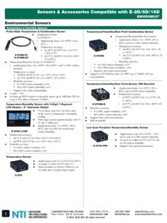
2 Features: Monitors the presence of 50-250 VAC 2-position screw-terminal connection Supports 2-wire sensor cable up to 1000 ft1 (6 foot cable included) RoHS and CE certified MATERIALS SUPPLIED E-ACVDRLY-yyy Voltage Detector (yyy= 515 or C14) E-2W-6 (6 foot 2-wire sensor cable) installation Place the E-ACVDRLY-xxx where it can be plugged into an AC power source (50-250 VAC). Connect a 2-wire (16-26 AWG) cable up to 1000 feet long between the + and ground ( ) terminals on the Voltage Detector and the same labeled DIGITAL IN terminals on the SYSTEM. 1 When using 2-wire cables longer than 100 ft, be careful to route cables away from AC wiring, lighting sources, electric motors, or other electrical devices.
3 2 Wire connections for E-16D Wire connections for E-2D/5D/MINI-LXO 3 The E-ACVDRLY-xxx can also be connected to the RJ45 SENSORS sockets of the E-16D/5D/2D. When using a CAT5 patch cable to make connection, you must first determine what wiring standard the cable has been made to. Make connections based on the chart below. TERMINAL ON E-ACVDRLY-xxx RJ45 Socket Pin # Cable Wire Color (T568A Standard) Cable Wire color ( T568B Standard) + 2 Green Orange 1 Green/White Orange/White Wire connections for E-MICRO-T(RHP) or E-1W(P) 4 Wire connections for E-16D/5D/2D using RJ45 Sensor sockets 5 OPERATION The E-ACVDRLY-xxx is designed to close the circuit between the + and terminals when AC Voltage is greater than 50 VAC and will open the circuit when AC Voltage is less than 45 VAC.
4 The PWR LED on E-ACVDRLY-xxx will illuminate when the circuit is closed. The circuit status can be monitored by the SYSTEM. Each SYSTEM can be configured to send alert notifications when the circuit opens or closes. Configuration of the E-ACVDRLY-xxx is done on the Digital Input Configuration page of the E-16D/5D/2D web interface and the Configuration page for the listed sensor in the E-MINI-LXO web interface. Configuration for the E-MICRO-T(RHP) and E-1W(P) is done on the Configure Alert page. A sample configuration page from the web interface for each product is shown below. Please refer to the appropriate section of the SYSTEM manual for additional information on the configuration pages.
5 Configuration page for E-16D/5D/2D or E-MINI-LXO Configuration page for E-MICRO-T(RHP) or E-1W(P) 6 installation NOTES It is not necessary to install an E-ACVDRLY-xxx to monitor the AC circuit which provides power to the E-16D/-5DB / -2DB. These models have built-in power monitoring and battery backup and will send an alert in the event of a power failure. In order for the ENVIROMUX System to send an e-mail alert, the attached Network components (routers, mail server, etc.) must have power . If you are using the SYSTEM and E-ACVDRLY-xxx to monitor the AC circuit providing power to any of these Network components, be sure they will not lose power during a fault condition.
6 (See image below.) FYI: In the images below, the E-5DB \-2DB are indicated because they include the battery backup feature to provide sensing and alert communication in the event of a SYSTEM power failure. If your Network components will lose power during the AC fault condition, use an alternate means to send alerts such as a GSM Modem (E-GSM) or Auto Voice Dialer (E-AVDS). The E-GSM and E-AVDS are powered by the Aux Pwr port on the E-16D/-5D(B)/-2D(B). (See image below.) If you are using the E-ACVDRLY-xxx to monitor the AC Circuit which provides power to the E-MINI-LXO or any of the necessary Network equipment (router, mail server, etc.)
7 , be sure they will not lose power during the AC fault condition. (See image below.) The method below would also be best suited for E-5D/ -2D (models without battery backup). 7 TECHNICAL SPECIFICATIONS COPYRIGHT Copyright 2009,2018 Network Technologies Inc All rights reserved. No part of this publication may be reproduced, stored in a retrieval system, or transmitted in any form or by any means, electronic, mechanical, photocopying, recording, or otherwise, without the prior written consent of Network Technologies Inc, 1275 Danner Drive, Aurora, OH 44202. CHANGES The material in this guide is for information only and is subject to change without notice.
8 Network Technologies Inc reserves the right to make changes in the product design without reservation and without notification to its users. WARRANTY INFORMATION The warranty period on this product (parts and labor) is two (2) years from date of purchase. Please contact Network Technologies Inc at (800) 742-8324 or 330-562-7070 for information regarding repairs and/or returns. A return authorization number is required for all repairs/returns. MAN081 Revised 4/2/2018 DESCRIPTION SPECIFICATION Input Voltage Range 0-250 VAC power Powered by 35-250 VAC via power cord (25mA Max.) Size (In.) W x D x H