Transcription of AC500 PLCs 4 - ABBPLC.com
1 44AC500 PLCsLow Voltage Products & Systems PLCsIndexAC500 grows to meet requirements .. ordering data .. - .. - .. information .. bus DP .. data .. - Automation (877) 268-3700 Low Voltage Products & Systems AC500 PLCsClear advantages thanks to clear structures Flexibility as program Thanks to its scalability, the AC500 PLC can be adapted to the most different automation tasks: The devices concerned can be used and combined in a flexible way. The number of different parts to be kept in stock is correspondingly mini-mized. The AC500 s system architecture CPUs CPUs are available in the performance classes PM571, PM581 and PM591, can all be programmed in five different languages, and provide an LCD display, an operator keypad, an SD card slot, andtwo integrated serial interfaces. The CPUs can be simply plugged onto the CPU terminal base.
2 Optionally,they are also available with integrated Ethernet or ARCNET. The CPU terminal base Available in three different versions, enables easy plugging of the CPU and one, two or four communication modules. The I/O modules Digital and analog in different versions. Can be simply plugged onto the terminal units for local expansion of the CPU (max. seven modules) and decentralized expansion via the FBP interface. Flexible use thanks to configu-rable channels. The terminal units Multi-purpose usage for both digital and analog I/Os, for 1, 2 and 3-wire designs. Enable simple prewiring without electronics. For 24 V DC and 230 V AC, optionally for spring or screw-type terminals. The communication modules For connection to standard field bus systems and integration into existing networks. Up to four communication modules in any desired combination are allowed at one CPU, resulting in a high degree of communication.
3 The FBP interface module With embedded digital I/Os and a field-bus-neutral interface for connecting the chosen FBP connector. For decentralized expansion by up to seven I/O modules. The SD card Optional for data logging, downloading and uploading the user program without a PC or a firmware update for all devices (CPU, couplers or I/O modules).213154671 Back-lighted LCD display and keypad 2 SD card slot 3 Plug-in communication modules (1 to max. 4) 4 Optionally with integrated Ethernet or ARCNET 5 FBP interface (for slave) 6 Two serial interfaces for programming, ASCII, Modbus or CS31 field bus (master)7 Expandable by up to seven local I/O modulesGeneral informationGross Automation (877) 268-3700 PLCsLow Voltage Products & Systems grows to meet requirementsControl + communication: Decentralized expansion:Centralized expansion:Gross Automation (877) 268-3700 Low Voltage Products & Systems AC500 PLCsNetworkedNetwork ModemGross Automation (877) 268-3700 PLCsLow Voltage Products & Systems Builder AC500 Control Builder AC500 is the engineering tool for all CPU performance classes of the AC500 , designed for standardized IEC 61131-3 programming in five different languages.
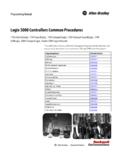
4 Other features of this tool are: Configuration of the over-all system including field buses and interfaces, extensive diagnostic func-tions, alarm handling, integrated visualization and open software in conformity with IEC 61131-3 Besides the suitable hardware, a high-performance, user-friendly and convenient engineering tool is indispensable for simple planning, pro-gramming, testing and commissioning of an automation applica-tion. AC500 Control Builder provides the following functionalities: Five standardized programming languages: Function Block Diagram (FBD), Instruction List (IL), Ladder Diagram (LD), Structured Text (ST), Sequen tial Function Chart (SFC) Free graphical function chart (CFC) Debugging functions for the program test: - Single step - Single cycle - Breakpoint Offline simulation IEC 61131-3 commands can be simulated without a PLC being con-nected, including the relevant malfunctions.
5 After the program test, the application can be downloaded to the control system. Sampling trace Timing diagrams for process variables and stor-age of data in a ring buffer with event management and watch lists Values of selected variables are displayed. Pre-defined values can be assigned to variables which can then be downloaded to the control sys-tem all at once ( Write recipe ). Ongoing values from the control system can also be pre-assigned for reading into the Watch and Recipe Man-ager, and stored in memory there ( Read recipe). These functions are also helpful, for example, for setting and entering control parameters. Visualization Includes color change, moving elements, bitmaps, text display, allows input of setpoint values and display of process variables read from the PLC, dynamic bar diagrams, alarm and event management, function keys and ActiveX of the communication interfaces For PROFIBUS DP, CANopen, DeviceNet, Ethernet, Modbus and CS31.
6 Open interfaces DDE and OPC. Programming Serial or via Ethernet or ARCNET networks. Engineering interface Provides access from the programming system to an external project database in which the program source code of one or several automa-tion projects is managed. Optionally, a version control system, such as Visual Source Safe, can be used in order to ensure data consis-tency of the program code for several different users and projects. Comprehensive libraries. Windows 32-bit standard. Operating systems Windows NT, 2000 and XP. Member of Automation AllianceProgrammingGross Automation (877) 268-3700 Low Voltage Products & Systems AC500 PLCsEthernetEthernet operates with a data rate of 10 MBit/s and as Fast-Ethernet with 100 MBit/s. Ethernet utilizes the producer/consumer model. This means that every station possesses equal rights.
7 While it is transmitting, all other stations listen in and accept the data directed to them. Bus access is regulated by the CSMA/CD procedure (Carrier-Sense Multiple-Access with Collision Detection), where each station may autonomously transmit when the bus is free. If a collision occurs, if two stations begin to transmit simultaneously, both of them will stop transmis-sion and wait for a randomly determined time before they transmit again. Eth-ernet defines the Layers 1 (Physical Link) and 2 (Data Link) of the OSI model. The AC500 supports transmission and reception of data using TCP/IP and/or UDP/IP. Further application layers can be implemented by subsequent loading. Simultaneous operation of TCP/IP, UDP/IP and application layer is also assured. The IP, TCP, UDP, ARP, RP, BOOTP, and DHCP protocols are supported as a standard feature, as application layer or ring-shaped using Ethernet hub or switch.
8 Data transmission Max. 10 MB/s with 10 Base T and max. 100 MB/s with Fast-Ethernet. Transmission media Twisted-pair cables with RJ45 connector. The maximum cable length is 100 m for 100 MB/s. DiagnosticsDetailed diagnostic messages for rapid trouble-shoot-ing are shown on the CPU addition, the device status is indicated at the com-munication module by four LEDs. CommunicationEthernetGross Automation (877) 268-3700 PLCsLow Voltage Products & Systems Field Bus - Decentral Periphery PROFIBUS DP is an open, high-speed and widely-used field bus. It provides multi-master and master-slave communication in the field area. This field bus can accordingly be used for AC500 and AC31 control system series and for field-bus-neutral FBP devices (decentralized I/Os and intelligent switching devices) via the PROFIBUS-FBP The masters rule data traffic on the bus.
9 When in possession of the bus access authorization (token), the masters can transmit data without an external request. The passive devices, known as slaves, do not receive any bus access rights; they acknowledge messages received, or respond to a query from a master. Baud rates from kBaud to 12 MBaud are supported. A maximum of 126 devices can be operated on the bus. Data exchange This is handled predominantly in cyclical mode be-tween master and slave. The requisite communication functions have been specified by the PROFIBUS DP basic functions in accordance with EN 50170. Each master has full write and read access to its assigned slaves, but only read access to the slaves assigned to other bus masters. There is no direct data exchange between masters. Acyclical services (DP-V1) for parameterization and diagnostics between master and slave are also available.
10 This is performed in parallel to the master s cyclical user data DP the functionality at a glance Max. 126 subscribers via amplifier and max. 32 subscribers (master/slaves) per bus segment Data transmission rate from max. 12 MBit/s with a cable length of 100 m, up to kBit/s with 1200 m Multi-master or master/slave communication. Bus access of the masters using token Connection of the master CPU and the associated communication module via a 9-pole SUB-D plug connector. Connection of slaves (CPU, I/Os and intelligent switching devices) via FieldBusPlug The system cable is a shielded twisted-pair line or a fiber-optic cable; transmis-sion standard EIA RS485 Diagnostics Detailed diagnostic messages for rapid trouble-shooting are shown on the CPU display. In addition, the device status is indicated at the communica-tion module by four LEDs.