Transcription of Accessories - esapyronics.com
1 AccessoriesPressure regulatorsZero Governors (EN88/1)BZR-REG-II (E5102 rev. 02 - 02/11/2017)BZR-REG-II E5102 rev. 02 - 02/11 :CONTACTS / SERVICE:Headquarters:Esa Enrico Fermi 4024035 Curno (BG) - ItalyTel + Sales:Pyronics International Zoning Industriel, 4 me rueB-6040 Jumet - BelgiumTel + Fax regulators and associated safety devices forgas appliances - Part 1: Pressure regulators for inlet pres-sures up to and including 50 kPa. Certificato CE-51CP4479 GENERAL WARNINGS: All installation, maintenance, ignition and setting mustbe performed by qualified staff. Read the instructionsbefore use. This control shall be installed in accordance with the rules in force. T o avoid damage to people and things, it is essentialto observe all the points indicated in this handbook. Thereported indications do not exonerate the Client/Userfrom observing general or specific laws concerning acci-dents and environmental safeguarding.
2 The operator must wear proper DPI clothing (shoes, ) and respect the general safety, preventionand precaution norms. T o avoid the risks of burns or high voltage electrocu-taion, the operator must avoid all contact with the burnerand its control devices during the ignition phase andwhile it is running at high temperatures. All ordinary and extraordinary maintenance must beperformed when the system is stopped. T o assure correct and safe use of the combustionplant, it is of extreme importance that the contents of thisdocument be brought to the attention of and be meticu-lously observed by all personnel in charge of controllingand working the devices. The functioning of a combustion plant can be dange-rous and cause injuries to persons or damage to equip-ment. Every burner must be provided with certified com-bustion safety and supervision devices.
3 The burner must be installed correctly to prevent anytype of accidental/undesired heat transmission from theflame to the operator or the equipment. The performances indicated in this technical docu-ment regarding the range of products are a result ofexperimental tests carried out at ESA-PYRONICS. Thetests have been performed using ignition systems, flamedetectors and supervisors developed by ESA-PYRO-NICS. The respect of the above mentioned functioningconditions cannot be guaranteed if equipment, which isnot present in the ESA-PYRONICS catalogue, is dispose of the product, abide by the local legislationsregarding :GENERAL NOTES: In accordance to the internal policy of constant quali-ty improvement, ESA-PYRONICS reserves the right tomodify the technical characteristics of the present docu-ment at any time and without warning.
4 It is possible to download technical sheets which havebeen updated to the latest revision from the The products manufactured by ESA-PYRONICS have been created in conformity to the UNI EN 746-2:2010 Norms: Equipment for industrial thermal process- Part 2: Safety requirements for combustion and themovement and treatment of combustible elements. Thisnorm is in harmony with the Machine Directive2006/42/CE. It is certified that the products in questionrespect all the requirements prescribed by the abovementioned Norms and Directives. Certified in conformity with the UNI EN ISO 9001 Norm by DNV products conform to the requests for the Euroasia market(Russia, Belarus and Kazakhstan).BZR-REG-II E5102 rev. 02 - 02/11 BZR-REG-II pressure regulators have been desi-gned according to the EN88/1 Norm and are ideal forapplications with burners, gas mixers and proprotionalmixers as they allow fuel flow regulation and maintainthe fuel/combustion agent ratio stable throughout thewhole regulation range.
5 The regulor is driven by a pres-sure signal that is proprotional to the actual combustionair pressure and retsores the same pressure value onthe gas line. There is a verison that can be used with gasup to 100 C. Gas regulation on venturi mixers. Gas regulation on proportional mixers. Gas regulation on all types of burner feeding STANDARD: Regulator group:2 Gas family: 1/2/3 Maximum working pressure:200mbar Nominal working pressure:80 200mbar W orking temperature:-10 C 60 C Maximum fluid temperature:50 C Flow ratio:100:1 Maximum differential pressure36 mbar Maximum air signal:70 mbar Minimum air signal:0,4 mbar Precision:at low flow mbarat full flow mbar S pring regulation field:+3 mbar / -5mbar * Regulation ratio:1 : 1 MATERIAL COMPOSITION: V alve body and seat:GAlSi V alve disc:AISI303 Bearing shaftgalvanized iron Diaphragms: Material approved according to EN549 BZR-REG-II-HT HIGH TEMPERATURE: Regulator group:2 Gas family: 1/2/3 Maximum working pressure:200mbar Nominal working pressure:80 200mbar W orking temperature:-10 C 60 C Maximum fluid temperature:50 C Flow ratio.
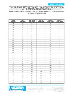
6 100:1 Maximum differential pressure36 mbar Maximum air signal:70 mbar Minimum air signal:0,4 mbar Precision:at low flow mbarat full flow mbar S pring regulation field:+3 mbar / -5mbar * Regulation ratio:1 : 1 MATERIAL COMPOSITION V alve body and seat:GAlSi V alve disc:AISI303 Bearing shaftgalvanized iron Diaphragms: Material approved according toEN549 Tmax=200 CNB: * only at maximum flowBZR-REG-II E5102 rev. 02 - 02/11 BZR-REG-II12 BZR-REG-II8 BZR-REG-II6 BZR-REG-II1101101001000 FLOWCHARTG5102I01 Natural gas flow @ 20 C [Nm3/h]Differential pressure [mbar]DESCRIPTIONThe balanced modulators or zero governors reduce thefluid pressure to the atmopheric pressure or charge units have twi diaphragms:- The first diaphragm, called balancing diaphragm, ismeant to separate the inlet gas chamber of the valve bodyfrom the underlying chamber of the main The second diaphragm, called main diaphragm is meantto balance the outlet pressure exisisting in the underlyingchamber of the diaphragm and the pressure existing inthe upper spring on these regulators is needed to counterba-lance the weight of the internal mobile parts and has anadditional voltage which is just enough to close upper chamber of the main diaphragm commu-nicates with the atmosphere or the pilotage pressure.
7 Thelower chamber instead, communicates via a pulse holewith the regulated pressure chamber downstream thevalve. When a there is a pressure difference between the upperchamber and lower chamber of the main diaphragm (posi-tive pressure in the upper chamber caused by the pressu-re charge or drop in the lower chamber caused by thesucntion of a venturi mixer), the valve moves downwardsthus allowing the gas to flow through the gas flow increses until the downstream pressure isequal to the existing pressure in the upper chamber; thisis possible because the downstream pressure, via thepulse hole, is transmitted in th elower chamber of the altering the pilot pressure (charge or drop) an imbalan-ce is caused between the existing pressures in the cham-bers. forcing the valve to open further until the systemrebalanced.
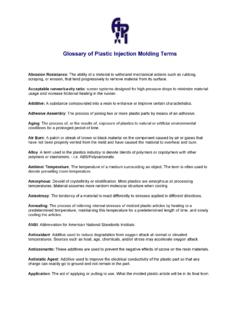
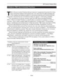
8 The regulator design ensures precision throu-ghout the entire flow BZR REG II regulators ensure a reliable and exactgas flow control for all types of combustion E5102 rev. 02 - 02/11 EXAMPLESAIR INLETGAS INLETHV01 FCV02HV04 PCV06FE05SV07SV07 SSFCV08RL09 IGNDETBMS11BT10BE03D5102I01 The BZR REG-II regulator is balanced when the gaspressure on the regulator oultlet is the same as the loa-ding pressure coming from the air air interception valveFCV2 Motorized air valveBE3 BurnerHV4 Manual gas interception valveFE5 p gas measurement calibrated orificeFCV6 Zero governorSV7 Safety solenoid valveFCV8 Gas limiting deviceRL9 Impulse lineBT10 Ignition transformerBMS11 Flame control deviceFIG. 01 BZR-REG-II E5102 rev. 02 - 02/11 HOLE CLOSEDIMPULSE LINEINLET FROM AIRMIXERTO BURNERSPsFROM GAS LINEFROM AIR LINEPaDpPrcPoutF5102I02F5102I03 REMOTE CONTROL REGULATOR - BZR-REG-II-RCAreas with very high ambient temperatures or placementof mixers in places that are difficult to reach, require verylong piping between the gas pressure regulator and results in problems such as reduced flow rates, dela-yed system responses and pressure drop along the pipe-line to be considered in dimensioning the lines.
9 In thesecases a controller with remote control BZR-REG-II-RC regulator with remote control works as a standardzero-governor, with the only difference that the regulatorpulse hole is factory closed and the lower diaphragmchamber is connected to the pipe on a downstream sec-tion of the controller, close to the mixer (see ).Below is the flow schme typical of a BZR-REG-II-RCpressure regulator:fig. 01 Said:Ps= Input pressure to the pressure regulatorPa= Loading pressure from the air pipeDp= Loss of load between controller and remote controlpositionPout = Output pressure to the pressure regulatorPrc = Pressure controlled by the instrument, comingfrom the remote controlThe downstream pressure of the remote control (Prc) isthe same as using a standard unit and corresponds tothe impulse loading pressure from the air line (Pa).
10 Prc = PaThe regulator works correctly when the inlet pressure ishigher than the output pressure of at least = Pout + 10mbarWhen adjusting the pressure upstream of the regulatorand its impulse pressure, the pressure drop between thecontroller and the remote control pipe position must betaken into = Prc + DpGenerally, note the loading pressure Pa, follow the follo-wing formula for calculating the required pressureupstream of the regulator:Ps = Pa + Dp + 10mbarOn the contrary, note the pressure upstream of the pres-sure regulator Ps, the maximum loading pressure to beapplied to the regulator is:Pa = Ps - Dp - 10mbarInput pressure to the regulator and pulse loading pres-sure must not exceed certified E5102 rev. 02 - 02/11 - The correct working position is vertical with piping pla-ced horizonatlly on a flat surface. Horizonal mounting withvertical piping is also - The arrow on the valve bodies indicates the flow - The regulators must not be installed in areas with tem-peratures higher than the maximum working -For installation on the piping, use tapered threadsaccording to ISO7/1, using opportune thread seal - Make sure there is a part of the piping upstream anddownstream the regulator of at least - For the connection of the reguator pulse signals, usemetallic pipes with an internal section of at least that the piping has not been crushed, flattened ordeformed as this could affect the correct transmission ofthe instrument s signal.