Transcription of ACCIDENT DETECTION AND ALERTING SYSTEM USING GPS …
1 6 ACCIDENT DETECTION AND ALERTING SYSTEM USING GPS & GSM Ajith , , , *4 1,2,3 UG Scholar ,4 Assistant Professor ,Department of Electrical and Electronics Engineering, Vel Tech Multi Tech Engineering College, Avadi, Chennai-62, Tamil Nadu, India. Abstract Nowadays we are able to track vehicles USING many applications which helps in securing personal vehicles, public vehicles, feet units and others. Furthermore there is a rapid increase in the occurrence of the Road ACCIDENT . This paper is about a SYSTEM which is developed to automatically detect an ACCIDENT and alert the nearest hospitals and medical services about it. This SYSTEM can also locate the place of the ACCIDENT so that the medical services can be directed immediately towards it. The goal of this paper is to build up a Vehicle accidental monitoring SYSTEM USING MEMS, GPS and GSM Technology.
2 The SYSTEM comprises of accelerometer, MCU, GPS & GSM Module support in sending message. The accelerometer is used to detect fall and Threshold Algorithm are used to detect ACCIDENT . Short Message will contain GPS[Latitude,Longitude]which helps in locating the vehicles. Index Terms MEMS Accelerometer, GPS, GSM . I. INTRODUCTION The usage of auto mobiles has improved linearly over the past decade, which increased in the risk of human life. This is because due to the insufficient emergency facilities .In this paper we are USING a alarm SYSTEM which helps in improving the emergency SYSTEM of the ACCIDENT SYSTEM . This SYSTEM detects the ACCIDENT occurrence and the co-ordinated of the ACCIDENT are messaged to the rescue team .A switching SYSTEM is used switch off in case there are no causality.
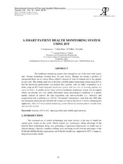
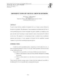
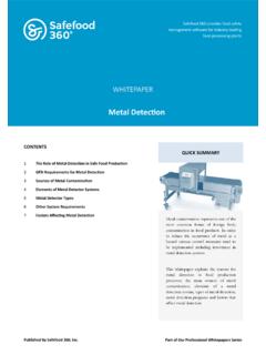
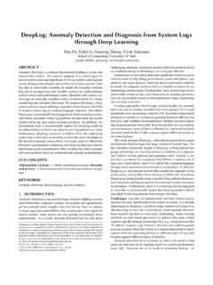
3 The ACCIDENT is detected with the help of MEMS Sensor and Vibration Sensor. The Angle in which the car has rolled off is indicated through a message. This Application helps in providing feasible solution to the poor emergency facilitates. Fig 1 : Road Accidents Year-wise 2001 - 2014 0200004000060000800001000001200001400001 6000018000020012002200320042005200620072 008200920102011201220132014 ROAD ACCIDENTSYEARI nternational Journal of Pure and Applied MathematicsVolume 119 No. 15 2018, 885-891 ISSN: 1314-3395 (on-line version)url: 5 Fig 2 : Road Accidents Based on Type Fig 3 : Road Accidents - CAUSE METHODOLOGY The Prototype of this ACCIDENT DETECTION and information passing technique uses the following steps: 1. The complete setup is depicted in the form of Block Diagram. 2. A Piezoelectric sensor detects the first occurrence of the ACCIDENT and it is intimated to the MCU.
4 3. The Latitude and Longitude are detected USING GPS and it is sent as message to the rescue team through GSM. 4. The message receiver number is pre stored in the EEPROM. 5. A OFF Switch is also provided at times of need to avoid false message. GSM Global SYSTEM for Mobile Communication In this paper GSM helps in controlling the DC motor, stepper motor, Temperature sensor and solid state relay by messaging schemes. This scheme helps in reducing the need of manual systems which are time consuming and not efficiency for usage. But the proposed SYSTEM is fully automatic and can function without any manual interruption. Hence this automatic SYSTEM is more efficient and less expensive and more convenient to use from were ever possible. Hence can be preferred mode of communication for controlling purpose.
5 GPS - Global Positioning SYSTEM GPS helps in both tracking and navigation purpose. Tracking systems is used to keep track of the vehicle without the intervention of the driver. But a navigation SYSTEM guides the driver to reach the destination without any disruptions. Both tracking and navigation uses the same architecture. As a ACCIDENT occurs the tracking stem detects the ACCIDENT prone vehicle and a message is sent to the rescue team through a call or SMS. LITERATURE SURVEY SpeedingOver-takingIntake of alcoholInternational Journal of Pure and Applied MathematicsSpecial Issue886 5 From the past event and the existing approach the below Drawback are been noted: 1. Manual SYSTEM is adopted. 2. Tracking of ACCIDENT is a crucial process in the SYSTEM . 3. Required medical attention cannot be given to the needed person.
6 4. Life loss and Property loss were not stopped in large scale. Considering all the drawbacks into account we have formulated a proposed SYSTEM which covers all the above mentioned drawbacks. 1. A Automated SYSTEM is used once the ACCIDENT occurs. 2. This SYSTEM gives the Latitude and Longitude of the SYSTEM ACCIDENT occurred area without any delay. Human life can be saved USING this auto mated SYSTEM . HARDWARE DESCRIPTION The ARDUINO MEGA BOARD 2560 is an open source electronic platform which supports both ADC and DAC conversions. Its software Arduino IDE version is used for programming the board. We can be infer that GSM ACCIDENT detector , the IMU6050 accelerometer and gyroscope are used to detect the posture of motion. In the proposed scheme, the gyroscope is to acquirethe tilt angle, , pitch, of the vehicle.
7 This is because when the elderly is suffering an ACCIDENT event, the vehicles tends to lie down, and the pitch angle is usually small. Actually, the work of acquiring the pitch angle of the vehicle can also be accomplished by USING a gyroscope which provides the angular acceleration information of the GSM. Furthermore, the tilt angle pitch angle of the Vehicle is estimated by USING the IMU6050 in conjunction with the accelerometer. The gyroscope helps in calculating pitch angle which helps in applying the proposed algorithm. AT MEGA 2560 MICRO CONTROLLER The Arduino Mega ATmega2560 is a development board developed for projects by an Italian company named Arduino , providing an open-source hardware and software ecosystem. The main purpose of the Arduino is to communicate with the electronic devices and achievemanyprocedures in the real world.
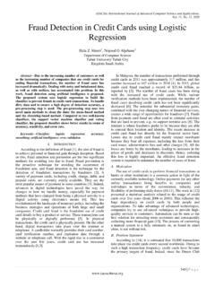
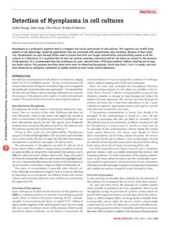
8 Block Diagram Of Proposed SYSTEM . IMU6050 Vibration Sensor Arduino MEGA 2560 Power Supply GSM LCD GPS International Journal of Pure and Applied MathematicsSpecial Issue887 5 The Arduino platform has a built-in Integrated Development Environment called IDE. It helps to program any project with various other devices . It supports C & C+ Language which are the foundation of all other programming . This board is particularly chosen as it provides the flexibility to communicate with more devices. The board is connected through a USB printer cable to the programming console. The Arduino IDE is the open-source software platform that connects to the Arduino hardware to upload programs and communicate with them. The board supports 54 digital I/O pins. 15 pins = PWM outputs 16 pins = Analog 4 USARTs hardware serial ports One power jack One USB connection One 16 MHz Crystal oscillator ICSP header and a reset button.
9 SIM800A GSM SIM800A is most used GSM module in Arduino community. SIM800A is easily interactes with Arduino which is more easy for begineers. The below table shows interaction of GSM and Arduino. SIM800A 5v/4v Arduino 5v SIM800A GND Arduino GND SIM800A SIM_TXD Arduino D8 SIM800A SIM_RXD Arduino D7 LCD (20 *4) The LCD display is a display device which that is used to print text, make custom characters, bink text, and position text. The display is 20X4 matrix which means that the LCD has 4 rows and 20 columns. Thus, it can display 80 characters at once. LCD is a flat-panel display that uses the light-modulating properties of liquid crystals. Liquid crystals uses a backlight or reflector to produce images in colour or monochrome. LCDs display arbitrary. UBLOX NEO 6M GPS RECEIVER MODULE Ublox NEO 6M is a standalone GPS receiver designed for low power consumption and low cost.
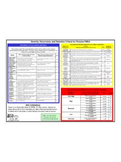
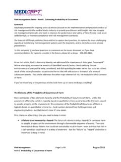
10 This module can withstand environmental conditions and electrical testing when performed for road vehicles. The receiver is of the dimension x x mm, which is a 24 pin LCC (Leadless Chip Carrier) package. The module has the ability to interface serially in various forms as mentioned below. Flow Diagram of ACCIDENT DETECTION SYSTEM NO YES YES START CHECK CONNECTIVITY AND RESPONSE OF SENSORS OBSERVE FOR ANY ACCIDENT OCCUR THROUGH MEMS SENSORS READING ACCIDENT OCCURS? TRIGGER ALARM & SEND MESSAGE TO RESCUE TEAM FALSE ALARM International Journal of Pure and Applied MathematicsSpecial Issue888 5 CIRCUIT DIAGRAM Fig 4 : Schematic diagram in real-time Proteus software ADVANTAGES operation. 2. Highly seure. and Reliable Design. both GSM&GPM LIMITATIONS 1. Network is must.