Example: bachelor of science
Accuphase
Butterworth Low-Pass Filter 5-Pole Butterworth Low-Pass Filter 5-Pole Butterworth Low-Pass Filter 5-Pole Butterworth Low-Pass Filter Balanced Conection Balanced Conection Balanced RX HS-LINK RX Coaxial TX Optical TX Coaxial RX Coaxial RX Optical RX Optical RX USB RX Coaxial RX COAXIAL 1 2 USB BALANCED HS-LINK OPTICAL OPTICAL 1 3 COAXIAL 2 ...
Tags:
Information
Domain:
Source:
Link to this page:
Documents from same domain

画期的な低雑音『Balanced AAVA ... - accuphase.co.jp
www.accuphase.co.jp伝統の美 アナログ・プリアンプの 最高位として、技術の粋を集め、選び 抜いた素材など全てに贅を尽くしたc-3850は、ゴールド調の

INTEGRATED STEREO AMPLIFIER - accuphase.co.jp
www.accuphase.co.jp2 integrted stereo amplifier a e-620 密閉されたラック等には絶対に設置しない。 通風が悪いと機器の温度が上り、火災や故障の原因

画期的な『AAVA-II方式 ... - accuphase.co.jp
www.accuphase.co.jp16個の電流スイッチ (65,536通りの組み合わせ) ノブ位置と音量が同じになるように、 cpuが電流スイッチをon/off
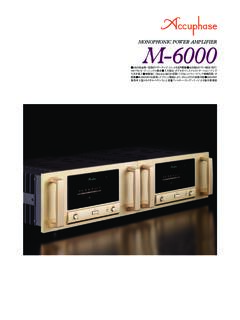
2台の完全同一回路のパワー ... - accuphase.co.jp
www.accuphase.co.jp2台の完全同一回路のパワーアンプ・ユニットを並列駆動 出力段は『パワーmos fet』 16パラレル・プッシュプル構成 入力部は、ダブルのインスツルメンテーション ・アンプ

DP-950/DC-950の詳細はこちら
www.accuphase.co.jp次世代の風格 dc-950は最高峰ディジタル・プロセッサー として、選び抜いた素材と高度なディジタル・ テクノロジーを駆使し、回路基板に《ガラス

www.accuphase.co.jp
www.accuphase.co.jp10 100 1k 10k 100k 16 12 8 4 0 -4 -8 -12 -16 増 強 した 減 衰 低音域 高音域
画期的な『AAVA方式ボリューム ... - accuphase.co.jp
www.accuphase.co.jpe-370のaava原理図 215 1 216 1 23 1 + 16種類の電流スイッチ (65,536通りの組み合わせ) ノブ位置と音量が同じになるように、

www.accuphase.co.jp
www.accuphase.co.jpdp-900:sa-cd送信 ! dp-900の中央部には、超重量級ブリッジと一体化した《高剛性・高精

画期的な『AAVA方式ボリューム ... - accuphase.co.jp
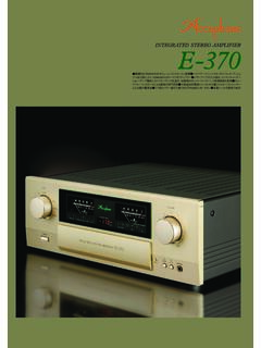
www.accuphase.co.jp画期的な『aava方式ボリューム・コントロール』搭載 大電力トランジスターのパラ レル・ プッシュプル出力段により90w/8Ω×2のハイクオリティパワー パ ワーアンプ部は、インス

高性能・高音質『AAVA方式 ... - accuphase.co.jp
www.accuphase.co.jp高性能・高音質『aava方式ボリューム・コントロール』搭載 左右独立の電源 トランス プリアンプのゲイ ン選択可能 ユニット・アンプ化した各増幅回路をボー
Related documents
Signal Processing - Rutgers University
www.ece.rutgers.edu11.6.1 Analog Lowpass Butterworth Filters, 594 11.6.2 Digital Lowpass Filters, 599 11.6.3 Digital Highpass Filters, 603 11.6.4 Digital Bandpass Filters, 606 11.6.5 Digital Bandstop Filters, 611 11.6.6 Chebyshev Filter Design∗, 615 11.7 Problems, 628 12 Interpolation, Decimation, and Oversampling 632 12.1 Interpolation and Oversampling, 632

EE648 Chebyshev Filters 08/31/11 John Stensby
www.ece.uah.eduoff” is faster) than can be achieved by the same order Butterworth filter. Type I Chebyshev Low-Pass Filter A Type I filter has the magnitude response 2 a 22 N p 1 H(j ) 1T(/ ) Ω= +ε Ω Ω, (1.3) where N is the filter order, ε is a user-supplied parameter that controls the amount of pass-band ripple, and Ωp is the upper pass band edge ...

Microwave Discrete and Microstrip Filter Design - Chapter 6
www.keysight.comMar 10, 2021 · The simulation of the lumped element model shows that the lowpass filter has a cutoff frequency of about 2 GHz and has a gentle roll off, which is expected for a Butterworth filter. Layout Simulation Steps for Distributed Low Pass Filter Calculate the physical parameters of the distributed lowpass filter using the design procedure given above.

KAAP686 Mathematics and Signal Processing for …
www1.udel.eduApr 27, 2011 · The zero-phase Butterworth filter has a response closer to unity in the passband, and closer to zero in the stopband, than either the moving average or the RMS filter. The cutoff frequency for the RMS filtered (defined as the frequency where attenuation=0.71) is very slightly lower than for the moving average filter with the same width.

Active Low-Pass Filter Design (Rev. B) - TI.com
www.ti.comButterworth filter defines a transfer function that can be realized by many different circuit topologies (both active and passive), while the MFB or Sallen-Key circuit defines an architecture or a circuit topology that can be used to realize various second-order transfer functions.

Active Filter Design Techniques
www2.seas.gwu.eduThe Butterworth low-pass filter provides maximum passband flatness. Therefore, a But-terworth low-pass is often used as anti-aliasing filter in data converter applications where precise signal levels are required across the entire passband.
CHAPTER 8 ANALOG FILTERS
www.analog.comband (or the −3 dB point for a Butterworth response filter). The stop band frequency (Fs) is the frequency at which the minimum attenuation in the stopband is reached.

Butterworth Filter - Islamic University of Gaza
site.iugaza.edu.psButterworth filter Example: Design a lowpass Butterworth filter with a maximum gain of 5 dB and a cutoff frequency of 1000 rad/s at which the gain is at least 2 dB and a stopband frequency of 5000 rad/s at which the magnitude is required to be less than −25dB. Solution: p= 1000 rad/s , s= 5000 rad/s, By normalization,