Transcription of Activated Sludge Calculations with Excel - CED Engineering
1 Activated Sludge Calculations with Excel Course No: C02-035 Credit: 2 PDH Harlan H. Bengtson, PhD, Continuing Education and Development, Inc. 9 Greyridge Farm Court Stony Point, NY 10980 P: (877) 322-5800 F: (877) 322-4774 Activated Sludge Calculations with Excel Harlan H. Bengtson, PhD, COURSE CONTENT 1. Introduction The Activated Sludge process is very widely used for biological wastewater treatment. This course includes background on biological wastewater treatment, a general description of the Activated Sludge process , information about several variations of the Activated Sludge process , a discussion of design Calculations for an Activated Sludge aeration tank, and a discussion of Activated Sludge operational Calculations . Example Calculations and sample Excel spreadsheets for making the Calculations are also included. 2. Learning Objectives At the conclusion of this course, the student will Know the equation for biological oxidation and how it fits into the organic carbon cycle Know the equation for photosynthesis and how it fits into the organic carbon cycle Know the major components of an Activated Sludge wastewater treatment system Be able to describe the differences between an extended aeration and conventional Activated Sludge system Be able to describe the differences between a contact stabilization and conventional Activated Sludge system Be able to calculate the required aeration tank volume (in units) for a specified volumetric loading, hydraulic residence time, or aeration tank F:M ratio, if given suitable aeration tank influent and aeration tank parameter information.
2 Be able to calculate the required aeration tank volume (in units) for a specified volumetric loading, hydraulic residence time, or aeration tank F:M ratio, if given suitable aeration tank influent and aeration tank parameter information. Be able to calculate the required Activated Sludge recycle flow rate, waste Activated Sludge flow rate, and aeration tank F:M ratio, if given suitable wastewater stream and aeration tank information along with the desired value for Sludge retention time. 3. Topics Covered in this Course I. Biochemical Oxygen Demand as a cause of Water Pollution II. Activated Sludge Background III. Activated Sludge process Variations IV. Activated Sludge Parameters V. Activated Sludge design Calculations VI. Activated Sludge Operational Calculations VII. Explanation of Equations for Qw and Qr VIII. Summary IX.
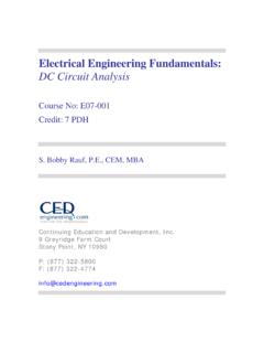
3 References 4. Biochemical Oxygen Demand as a Cause of Water Pollution Biochemical oxygen demand (BOD) is an indirect measure of the concentration of biodegradable organic matter in water or wastewater. Organic matter (as measured by BOD) is one of the major constituents removed from wastewater in domestic wastewater treatment plants. The reason for being concerned about organic matter in water is its effect on dissolved oxygen in the receiving stream. Dissolved oxygen in water is essential for much of aquatic life, so organic contaminants that affect dissolved oxygen level in water are of concern. The death and decay portion of the organic carbon cycle shown in the above diagram is the portion that takes place in the biological treatment portion of a wastewater treatment plant or else takes place in the receiving stream if the organic matter isn t removed in the treatment plant.
4 The two major reactions that take place in the organic carbon cycle are biological oxidation of waste organic matter and photosynthesis, which is the process by which green plants produce organic matter from carbon dioxide and water in reactions that are catalyzed by sunlight and the chlorophyll in the green plants. Through the biological oxidation process , aerobic microorganisms utilize oxygen in breaking down organic matter to carbon dioxide and water together with small amounts of other end products. The photosynthesis and biological oxidation processes can be represented by the following two equations: Photosynthesis: CO2 + H2O + sunlight organic plant matter (primarily C, H, & O) + oxygen (catalyzed by the chlorophyll in green plants) Biological Oxidation: waste organic matter (primarily C, H & O) + O2 CO2 + H2O + energy This reaction is the death and decay shown in the organic carbon cycle diagram.
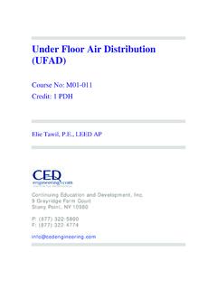
5 The process takes place as aerobic microorganisms utilize the waste organic matter as their food (energy) source. The process uses oxygen, so if it is taking place in a water body, dissolved oxygen is consumed. A large supply of organic matter in the water will result in multiplication of microorganisms and rapid removal of dissolved oxygen, leading to oxygen depletion below the level needed by aquatic life. This is also the process that takes place in biological oxidation processes in wastewater treatment plants for removal of organic matter from the incoming wastewater. 5. Activated Sludge Background The diagram below shows a general flow diagram with the typical components present in an Activated Sludge wastewater treatment plant. The first component is preliminary treatment, typically consisting of screening, flow measurement, and perhaps grit removal.
6 The second component, the primary clarifier, is used to remove settleable suspended matter. The underflow goes to Sludge treatment and disposal and the overflow goes to an aeration tank. The aeration tank is the heart of an Activated Sludge treatment process . It is here that biological oxidation of dissolved and fine suspended organic matter takes place. The biological oxidation takes place because aerobic microorganisms, organic matter and dissolved oxygen are all brought together in the aeration tank. The organic matter comes in with the primary effluent. The dissolved oxygen level is maintained by blowing diffusers. This also serves to keep the aeration tank contents mixed. A suitable concentration of microorganisms is maintained in the aeration tank by settling out the Activated Sludge (microorganisms) in the secondary clarifier and recycling them back into the aeration tank.
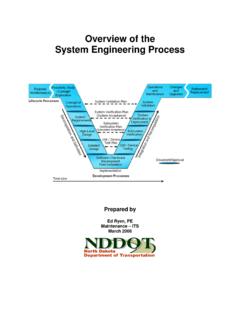
7 Air into the aeration tank through age Credit: Lee & Ro, IncIm 6. Activated Sludge process Variations our common variations of the Activated Sludge process are: Conventional Activated Sludge Activated Sludge brief description of each follows. he Conventional Activated Sludge process F Extended aeration Completely mixed The contact stabilization process A T is used over a wide range of wastewater flow rates, from small to very large plants. The flow diagram and general description are given above in the Activated Sludge Background section. The aeration tank in a conventional Activated Sludge process is typically designed with a long, narrow configuration, thus giving approximately plug flow through the tank. For large treatment plants, the aeration tank is often built with a serpentine pattern, like that shown in the diagram below, in order to obtain the desired plug flow without an excessive length requirement for the tank.
8 The Extended Aeration Activated Sludge process is shown in the diagram below. As you can see, this process doesn t use a primary clarifier. Instead, a longer detention time is used for the aeration tank, so that the settleable organic matter will be biologically oxidized along with the dissolved and fine suspended organic matter. This requires a hydraulic detention time of about 24 hours instead of the 6 to 8 hours that is typical for the conventional Activated Sludge process . This simplifies the operation of the plant by eliminating the primary clarifier and reducing the need for Sludge treatment and disposal to a very minimal flow of waste Activated Sludge that must be drawn off periodically. he Completely Mixed Activated Sludge process T has the same overall flow ypical applications of the completely mixed Activated Sludge process are pattern as the conventional Activated Sludge process .
9 The main differences are the method of aeration and the aeration tank configuration. For the completely mixed option, aeration is usually with a mechanical mixer, rather than with diffused air. Also, the tank configuration is usually approximately square, rather than long and narrow. This combination of mixing and tank configurations makes the aeration tank approximate a completely mixed reactor rather than the plug flow reactor approximated by the conventional Activated Sludge aeration tank. The flow diagram below illustrates this. Tcases where slug flows of high concentration, hard to oxidize, or toxic wastes enter the treatment plant. The complete mixing dilutes such flows into the entire tank contents more rapidly than a plug flow design , making the slug flow less likely to upset or kill the microorganisms. he Contact Stabilization Activated Sludge process T gets by with less total aeration tank volume than that needed for the conventional Activated Sludge process .
10 This is accomplished because the full wastewater flow is aerated for only to 2 hours in an aerated contact tank. This is sufficient time for removal of the organic matter from the wastewater flow by the microorganism. If those microorganisms were recycled directly into the aeration tank after settling out in the secondary clarifier, however, they would not continue to take up organic matter, because they are still full from the to 2 hour feast they recently had. If the recycle Sludge is aerated for 3 to 8 hours to allow the microorganisms to digest the organic matter that they ve taken up, then they go back into the aeration tank ready to go to work. Since the recycle Activated Sludge flow is less than the full wastewater flow, this results in less overall aeration tank volume for a given wastewater flow rate to be treated.