Transcription of Grounding System Theory and Practice - CED …
1 Grounding System Theory and Practice Course No: E04-027 Credit: 4 PDH Velimir Lackovic, Char. Eng. Continuing Education and Development, Inc. 9 Greyridge Farm Court Stony Point, NY 10980 P: (877) 322-5800 F: (877) 322-4774 Grounding System Theory and Practice Introduction System Grounding has been used since electrical power systems began. However, many companies and industrial plants have used System Grounding methods differently. The problem of whether a System neutral should be grounded, and how it should be grounded, has many times been misunderstood completely. Therefore, Grounding of many systems has been based upon past experience rather than engineering analysis. This course provides applicable information for Grounding , such as definitions, reasons for having a System ground, the most desirable Grounding method, and so on, and how to measure ground resistance in order to maintain the Grounding System .
2 The definition of Grounding is commonly used for both, System Grounding and equipment Grounding . The National electrical Code (NEC) defines System ground as a connection to ground from one of the current-carrying conductors of an electrical power System or of an interior wiring System , whereas an equipment ground is defined as a connection to ground from one or more of the noncurrent-carrying metal parts of a wiring System or equipment connected to the System . The following definitions describe power System Grounding . - System neutral ground: A connection to ground from the neutral point or points of a circuit, transformer, motor, generator, or System . - Grounded System : A System of conductors in which at least one conductor or point is intentionally grounded. - Ungrounded System : A System of conductors in which there is no intentional connection to ground.
3 - Solidly grounded: A System in which there is no intentional impedance in ground connection; in such a System the line to ground fault currents may equal three-phase fault current. - Resistance grounded: A System grounded through a resistance, the value of which can be such as to provide either a low- or high-resistance ground System . The low-resistance ground System can have from 25 to several thousand amperes (A) depending upon the value of the resistance. The high-resistance ground System usually has a value less than 25 A but greater than the value given by XCO/3, where XCO is the charging capacitance of the System . - Reactance grounded: A System grounded through a reactance. - Resonant grounded: The System Grounding reactance value is such that the rated frequency fault current flowing through it is substantially equal to the current flowing between the conductors and the earth (charging current of the System ).
4 - Ground-fault neutralizer: A Grounding device that provides an inductive component of current in a ground fault that is substantially equal to, and therefore neutralizes, the rated frequency capacitive component of the ground fault current. Selection of Grounding Method The selection of a method for power System Grounding is very difficult because a large number of factors must be considered before a power System Grounding method can be chosen. The following discussion outlines some problems with various Grounding methods and explains how and why Grounding systems are applied. Ungrounded Systems Early electrical systems were almost universally operated ungrounded. On small systems an insulation failure on one phase did not cause an outage. The failure could probably be found and repaired at a convenient time without a forced outage. This worked well as long as the systems were small.
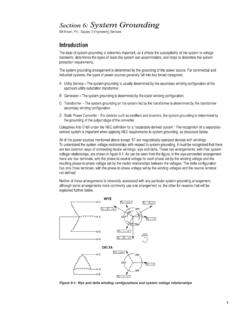
5 However, as systems increased in size and voltage rating, an increasing number of insulation failures produced multiple failures and major faults. At first, the reasons for these failures were not understood, and considerable work was done to find why they occurred. Figure 1 below shows a typical ungrounded neutral System . Figure 1. Ungrounded neutral System Actually, it is a capacitive grounded neutral System ; the capacitance being the conductor capacitance to ground. In normal operation, the capacitive current of all three lines is leading the respective line to neutral voltages by 90 , and the vector sum of all three currents is zero. Figure 2 shows what happens when the System of Figure 1 is accidentally grounded. Figure 2. Fault on ungrounded neutral System The charging current of the faulted phase goes to zero because its voltage to ground is zero. The voltages of the unfaulted phases increase to full line-to-line value with respect to ground, and their charging currents increase proportionally.
6 In addition, because of the 30 shift of the line voltages with respect to ground, the charging currents shift accordingly, and the sum of the charging currents in the unfaulted phases is three times the normal value and appears in the ground, returning to the System through the fault. If the fault can be interrupted, it will most likely be done at a current zero. However, since the current leads by 90 in the capacitive circuit, current zero occurs at the instant of a voltage maximum; thus, if the fault momentarily clears, a high voltage immediately appears across the fault, and restrike of the fault will probably occur. In the momentary interval of time that the fault has been cleared, the excessive voltage charge of the capacitors on the unfaulted lines has been trapped as a direct current (DC) charge. When the arc restrikes again, the capacitors are again recharged by a line-to-ground voltage added to the trapped charge.
7 Thus, a restrike after another current zero clearing is more inevitable, adding another charge. The phenomenon thus probably becomes an oscillating and self-perpetuating build-up in voltage, which eventually will lead to an insulation failure on another phase and a major two-phase fault. While the first failure may have been a tree branch in the line, the second failure may occur at some other location entirely, perhaps involving expensive equipment insulation, such as a transformer. Thus, the principal advantage claimed for the ungrounded System actually caused troubles that resulted in its abandonment. These troubles coupled with other factors led to the adoption of grounded neutral systems in some form. Some of the other factors are as follows: - Because of greater danger to personnel, code authorities frowned on ungrounded systems. - Equipment costs were generally lower for equipment rated for grounded neutral systems because of the reduction in insulation permissible.
8 Because graded insulation could be used, single-bushing, single-phase transformers could be used. - At the higher voltages being used today (69 kV and above), material savings in transformer costs can be realized by employing reduced basic insulation level (BIL). These savings are in addition to the modest savings above, and may amount to substantial savings in the cost of transformers in the various voltage classes with reduced insulation. The requirements for safely reducing insulation level demand that System neutrals be grounded. Thus, these savings are not available on the ungrounded System . Solidly Grounded Systems The simplest and most effective method of Grounding is to solidly connect the neutrals of any wye-connected transformers or generators to ground. This method has two major advantages: it is simple and inexpensive in that it requires no extra equipment.
9 It minimizes the magnitude of the overvoltage that will appear on the unfaulted phases during a ground fault, resulting in a reduction in the stress on insulation as compared with other methods. This is the reason that solidly grounded neutrals are a necessity where reduced BIL insulation is to be used. In spite of the advantages of the solidly grounded System , there are associated disadvantages such that other Grounding methods are often used. These disadvantages all stem from the fact that a solidly grounded System produces the greatest magnitude of ground fault current when a fault to ground occurs. It is realized that with a grounded neutral System perhaps 95% or more of all faults start as a single phase to ground fault. If the amount of ground current that flows can be controlled and the fault cleared promptly, the amount of damage at the fault will be reduced and the fault probably restricted so as not to involve more than one phase.
10 This may result in preventing bum downs, reduction in the cost of making repairs, and reduction in the frequency or extent of maintenance on the breakers that interrupt the fault. In the case of machines or transformers, the difference in repair cost may be that of replacing a few damaged coils as compared with completely replacing the machine or transformer, which may be necessary where oil fires and explosions follow the transformer fault, or where heavy fault currents melt down coils and burn and weld together expensive areas of laminated electrical steel in the transformer core or machine stator iron. Since the damage done is approximately proportional to I2t, it is obvious that much more can be done in the reduction of current than by reduction in time. Under certain conditions, single phase to ground faults can give rise to short-circuit currents 50% in excess of three-phase short-circuit current.