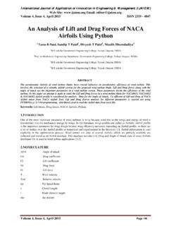
Transcription of AERODYNAMIC CHARACTERISTICS OF NACA 0012 AIRFOIL …
1 AERODYNAMIC CHARACTERISTICS OF NACA 0012 AIRFOIL SECTION AT DIFFERENT ANGLES OF ATTACK SUPREETH NARASIMHAMURTHY GRADUATE STUDENT 1327291 Table of Contents 1) 2) 3) 4) Conclusion ..9 5) List of Figures Figure 1: Basic nomenclature of an Figure 2: Computational Figure 3: Static Pressure Contours for different angles of Figure 4: Velocity Magnitude Contours for different angles of Fig 5: Variation of Cl and Cd with Figure 6: Lift Coefficient and Drag Coefficient Ratio for Re = List of Tables Table 1: Lift and Drag coefficients as calculated from lift and drag forces from formulae given 1 | P a g e Introduction It is a fact of common experience that a body in motion through a fluid experience a resultant force which, in most cases is mainly a resistance to the motion. A class of body exists, However for which the component of the resultant force normal to the direction to the motion is many time greater than the component resisting the motion, and the possibility of the flight of an airplane depends on the use of the body of this class for wing structure.
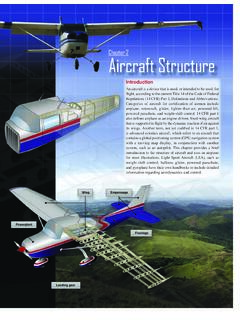
2 AIRFOIL is such an AERODYNAMIC shape that when it moves through air, the air is split and passes above and below the wing . The wing s upper surface is shaped so the air rushing over the top speeds up and stretches out. This decreases the air pressure above the wing . The air flowing below the wing moves in a comparatively straighter line, so its speed and air pressure remain the same. Since high air pressure always moves toward low air pressure, the air below the wing pushes upward toward the air above the wing . The wing is in the middle, and the whole wing is lifted. The faster an airplane moves, the more lift there is. And when the force of lift is greater than the force of gravity, the airplane is able to fly. Nomenclature of an AIRFOIL An AIRFOIL is a body of such a shape that when it is placed in an airstreams, it produces an AERODYNAMIC force. This force is used for different purposes such as the cross sections of wings, propeller blades, windmill blades, compressor and turbine blades in a jet engine, and hydrofoils are examples of airfoils .
3 The basic geometry of an AIRFOIL is shown in Figure 1. Figure 1: Basic nomenclature of an AIRFOIL The leading edge is the point at the front of the AIRFOIL that has maximum curvature. The trailing edge is defined similarly as the point of maximum curvature at the rear of the AIRFOIL . The chord line is a straight line connecting the leading and trailing edges of the AIRFOIL . The chord length, or simply chord is the length of the chord line and is the characteristic dimension of the AIRFOIL section. Foils are designed in a vast amount of ways. One difference in each is the camber, also called the curvature, on the upper and lower surfaces (upper and lower camber in Figure 1). Cambered foils tend to have a higher maximum coefficient of lift as it takes higher angles of attack to stall. A symmetric foil has zero camber and works much better than a highly cambered foil at lower angles of attack ( airfoils and Airflow 2005). These foils are often assigned numbers from the NACA corresponding to their properties.
4 NACA, the National Advisory Committee for Aeronautics was a research group which tested and developed many series of foils this group is now known as NASA. For the four digit numbers, the first number describes the maximum camber as a percentage of the chord length. The second number is the 2 | P a g e position of the maximum camber in tenths of the chord and the third and fourth number corresponds to the maximum thickness of the foil as a percentage of the chord length (NACA Profiles 2010). The well known NACA 0012 foil which will be used in this project is symmetrical as both first and a second number are zero, and has maximum thickness of 12% of the chord length. Angle of Attack As an AIRFOIL cuts through the relative wind, an AERODYNAMIC force is produced. This force can be broken down into two components, lift and drag. The lift produced by an AIRFOIL is the net force produced perpendicular to the relative wind. The drag incurred by an AIRFOIL is the net force produced parallel to the relative wind.
5 The angle of attack is the angle between the chord line and the relative wind. Most commercial jet airplanes use the fuselage center line or longitudinal axis as the reference line. It makes no difference what the difference line is as long as it used as consistently. As the nose of the wing turns up, AOA increases, and lift increases. Drag goes up also, but not as quickly as lift. During take-off an airplane builds up to a certain speed and then the pilot rotates the plane, the pilot manipulates the controls so that the nose of the plane comes up and, at some AOA the wings generate enough lift to take the plane into the air. Since an airplane wing is fixed to the fuselage, the whole plane has to rotate to increase the wing 's angle of attack. Front wings on racecars are fabricated so the angle of attack is easily adjustable to vary the amount of down force needed to balance the car for the driver. Objective In this project, the aim is to study the behavior of a NACA 0012 AIRFOIL at a Reynolds number of 50,000, at various angles of attack ranging from 0o to 16o.
6 From the literature the stall angle occurs between 10o and 16o. For each angle of attack, contours of static pressure and velocity magnitude are obtained along with lift and drag forces on the AIRFOIL . A graph of CL and CD vs angle of attack is plotted. 3 | P a g e Methodology Computational fluid dynamics simulations were used to investigate the AERODYNAMIC CHARACTERISTICS . The important components of the simulations include the mesh, definition of the boundary condition and the fluid model used in the simulation as a proper approximation. Coefficient of Lift and Drag The drag equation is, =12 2 Therefore, coefficient of drag is: =2 2 Where A for a 2D AIRFOIL is approximated as the chord length (1m), is the density ( kg/m3), and v is the relative velocity. The drag equation is essentially a statement that the drag force on any object is proportional to the density of the fluid and proportional to the square of the relative speed between the object and the fluid.
7 In fluid dynamics Cd is a dimensionless quantity that is used to quantify the drag or resistance of an object in a fluid environment such as air or water. It is used in the drag equation where a lower drag coefficient indicates the object will have less AERODYNAMIC or drag. The drag coefficients always associated with a particular surface area. The drag coefficient of any object comprises the effects of the two basic contributors to fluid dynamics drag: skin friction and from drag. The drag coefficient of a lifting AIRFOIL or hydrofoil also includes the effects of lift induced drag. The drag coefficient of a complete structure such as an aircraft also includes the effects of interference drag. The lift equation is =12 2 Therefore, coefficient of lift is: =2 2 A fluid flowing past the surface of a body exerts a force on it. Lift is the component of this force that is perpendicular to the oncoming flow direction. It contrasts with the drag force, which is the component of the surface force parallel to the flow direction.
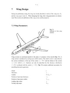
8 If the fluid is air, the force is called an AERODYNAMIC force. The lift coefficient of a fixed- wing aircraft varies with angle of attack. Increasing angle of attack is associated with increasing lift coefficient up to the maximum lift coefficient, after which lift coefficient decreases. As the angle of attack of a fixed- wing aircraft increases, separation of the airflow from the upper surface of the wing becomes more pronounced, leading to a reduction in the rate of increase of the lift coefficient. 4 | P a g e Initial and Boundary conditions The computational domain is as shown in figure 2. The domain is bounded on the inside by an AIRFOIL shaped closed path, and by a rectangular box on the outside, as sketched (drawing not to scale). Inlet Inlet Fig 2: Computational domain The AIRFOIL is assumed to have a chord length(c) of meters (all dimensions in this module are in the standard MKS system of units), with the leading edge of the AIRFOIL at (0,0,0) and the trailing edge at (1,0,0).
9 The computational domain extends far upstream of the AIRFOIL (8*c) where the boundary condition will be a velocity inlet. The angle of attack will be specified in the CFD flow solver, Fluent. Then flow is studied for angle of attack range of 0o to 16o for every 4o. The outlet is to the far right (12*c). The top and bottom of the computational domain are also taken to be inlet and are at a distance of 8 times the chord length (c) so that these boundaries do not interfere with the flow over the AIRFOIL . It is assumed that since the outer limits of the computational domain are so far apart, this AIRFOIL behaves as if in an infinite free stream. In order to adequately resolve the boundary layer along the AIRFOIL wall, grid points will be clustered near the wall. Far away from walls, where the flow does not have large velocity gradients, the grid points can be very far apart. A hybrid grid will be used in this problem, a structured quadratic (rectangular cells) grid around the AIRFOIL and outward to an ellipse, connected to an unstructured (triangular cells) grid out to the limits of the computational domain.
10 The boundary conditions were set up at the edge of the AIRFOIL and the boundary of the flow field. For the AIRFOIL , the boundary condition was set up as wall condition. For the inlet, the boundary condition was set up as velocity and Gauss pressure with velocity defined in magnitude and direction and pressure to be zero. For the outlet, the boundary condition was set up to be Gauss pressure being zero. The Inlet velocity was computed from a Reynolds number of 50000. The free stream velocity was found to be m/s. The velocity is specified by components, with the x component of velocity *cos( ) and y component of velocity being *sin( ), where is the angle of attack. 5 | P a g e Results Static Pressure Contours (a) (b) (c) (d) (e) (f) Fig 3: Static Pressure Contours for angle of attack of (a) 0o, (b) 4o, (c) 8o, (d) 12o, (e) 14o and (f) 16o 6 | P a g e For and angle of attack is zero degree we obtain that the contours of static pressure over an AIRFOIL is symmetrical for above and lower sections and the stagnation point is exactly at the nose of an AIRFOIL .