Transcription of AFWL-TR-65-161 FWL-TR161
1 AFWL-TR-65-161 FWL-TR161coEXPERIMENTAL STUDY OF STATICAND DYNAMIC FRICTION BETWEENSOIL AND TYPICALCONSTRUCTION MATERIALSG. A. LeonardsPurdue UniversitySchool of Civil EngineeringLafayette, India .. EC LEA R 1!4 c, ! .:. D-TECHNICAL REPORT NO. AFWL-TR-65-161 December 1965 AIR FORCE WEAPONS LABORATORYR esearch and Technology DivisionAir Force Systems CommandKirtland Air Force Base .New Mexico -'I" S .I4~.,-11"ApwL-TR-65-161R , -I Research and Teerhology .. iAR OIC .L r ATOIY-j AIR FORCE WIAC .. Air For-re Systems 0,.,.and-,D~ w .. Kirtlazi Air Force Base$ v. MexicoWhen U. S. Government drawings, specifications, or other data are used forany purpose other than a definitely related Government procurement operation,tb. Government thereby incurs no responsibility nor any obligation whatsoever,ad the fact that the Government may have formulated, furnished, or in any* way supplied the said drawings, specifications, or other deta, is not to beregarded by implication or otherwise, as in any manner licensing the holderor any other person or corporation, or conveying any rights or permission to* manufacture, use, or sell any patented invention that may in any way berelated report is made available for study with the understanding thatproprietary interests in and relating thereto will not be impaired.
2 Incase of apparent conflict or any othcr questions between the Government'srights and those of others, notify the Judge Advocate, Air Force SystemsCoimand, Andrews Air Force Base, Washington, D. C. of this document is STUDY OF STATIC AN'D D' NAHICFRICTION BETWEEN SOIL AND TYPICAL CONSTRUCTION MATERIALSG. A. LeonardsPurdue UniversitySchool of Ciril EngineeringLafayette, IndianaDistribution of this documentis !FOREWORDThis report was prepared by the School of Engineering, PurdueUniversity, Lafayette, Indiana, under contract AF 29(601)-5204. Theresearch was performed under Program Element , ProjectVi 5710, Subtask , and was funded by the Defense Atomic SupportAgency (DASA).Inclusive dates of research were 1 April 1962 to I April report was submitted 24 November 1965 by the Air Force WeaponsLaboratory project officer lLt John E. Seknicka (WLDC).
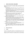
3 JO E. SEKNICKAILt, USAFP roject OfficerAYROBERT E. CRAWFORD JOHN W. KODIS(f Major, USAF Colonel, USAFD eputy Chief, Civil Engineering Chief, Development DivisionBranchiiABSTRACTA report is made of research carried out at Purdue University to determine, onthe basis of laboratory measurements, the coefficient of friction between two8sands of different gradation (one vith angular and the other with rcundedparticles) in contact with Portland cement mortar, steel, teflon, and the static tests, loads were applie. at a uniform rate until sLip occurredin approximately 5 minutes. Dynamic loa4. were applied by means of a shocktube, which produced a gcep-like forcing function; slip usually occurred inapproximately 2 milliseconds or less. It was foind that the coefficients offriction depend on the relative size, shape and surface roughness of the sandgrains with respect to that of the surface in question; when the sliding surfaceis "rough" in comparison with the sand particles, the coefficient of frictionapproaches the coefficient of internal friction of the sand.)
4 Both graphite andteflon serve as friction reducers, compared to the plain surfaces, irrespectiveof the rate at which slip is initiated. For plain steel or cement mortar, thedynamic coefficient of friczion was greater than the static coefficient offriction by about 25 percent, unless the static coefficient was such thatsand/sand slip was approached. The angle of shearing resistance of the sandthus provides an upper limit to the coefficient of wall friction at all ratesof page intentionally left OF CONTENTSS ection PageI INTRODUCTION..1II EXERIMENTAL CONCEPT .. 2 General Considerations ..2 Dynamic Friction Force .. 4 Inertia Force.. 6 Dynamic Nomal Force .. 6 III .. 7 Sand ..Test Rods ..9IV APPARATUS AND PROCEDURES .. 15 Sample Preparation .. 15 Static Tests ..o ..23 Dynamic Tests ..25V RESULTS ..32 Static Friction Tests..32 Dynamic Tests.
5 40VI CONCLUSIONS .. 53 REFERENCES .. 55 APPENDICES..A: DETERMINATION OF FORCING FUNCTION.. 56B: USE OF LINEAR VARIABLE DIFFERENTIALTRANSFORMER FOR VELOCITY MEASUREMENTS .58C: SAMPLE CALCULATIONS..62 Statir Tests .. 62 Dynamic Tests .64 DISTRIBUTION..66vVILIST OF TABLEST able No. PageI. Grain Size Distribution for 60-80 Sand ..7II. Types of Surfaces Tested .. 9 III. Comparison of Is Values for Different Types of TestsUsing 20-30 Sand ..33IV. Values of ps Based on Static Tests with 60-80 Sand ..37V. Values of ps Based on Static Tests with 20-30 Sand ..38VI. Comparison oflis Values..40 VII. 8Ns for Uncapped and Capped Gages at Time of Slip..45 VIII. Values of 4d for 60-80 Sand on Plain Steel ..46IX. Values of 9d for 20-30 Sand on Smooth Mortar ..47X. Values of P1d for 20-30 Sand on Rough Mortar..48XI. Values of Aid for 20-30 Sand on Teflon Coated SmoothMortar.
6 49 XII. Values of 4d for 20-30 Sand on Teflon Coated Steel ..50 XIII. Values of ld for 20-30 Sand on Graphite Coated SmoothMortar ..51 XIV. Comparison of Static and Dynamic Coefficients of Friction. 52viLIST OF FIGURESF igure Schematic Diagram of Experimental Concept.. 32. Forcing Functions, F(t).. 53. Failure Conditions at Peakcoi -C3 in the Triaxial Test,20-30 Sand ..84. Failure Conditions at Peakal -03 in the Triaxial Test,60-80 Sand ..105. Photomicrograph of Sands (Multiplication x 60) ..116. Test Rods ..o..147. Mold for Sample Preparation..168. Sand "Raining" Tube..179A. Stress Gage and Gage Placing Tool ..199B. Gage Locations ..2010. Sample Headcap ..2011. Extruding the Sample from the Mold ..2112. The Extruded Sample..2213. Sample Housing Showing Alignment Guides and Reaction Ring. 2214. Apparatus for Auxilliary Static Friction Tests.
7 2415. Proving Ring and Displacement Dial in Position forStatic Tests ..2616. Piston Assembly ..2717. LVDT Mounting..27].8. Dynamic Test Assembly .. 2819. Detail of Headcap..28viiLIST OF FITIUMS (continued)20. Gen eral View of Dynamic Test Set-Up..2921. Capped Stress Gage ..3122. Force vs. Displacement (60-80 sand on plain smwoth mortar)Static Test No. 7.. 3423. Force vs. Displacemnt (20-30 sard on plain rough rta-)Static Test lo. 14..3524. Force vs. Displacement (20-30 sand on Teflon coated steel)Static Test No. 35 ..3625. Typica!LVT Trace .. 4126. Typical Pres-se Gage Trace ..4127. 8N vs. Station Along Rod (at slip) .. 4328. Verificaticn Cmrves for F(t) .. 5729. Circuit Diagram for LVMT Used as a Velocity Transducer ..5930. Typical Trace for Velometer Calibration.. 6031. Vacuu Gage Calibration.. 63viii--~-- -- ~- ,------SECTION iIfRODUCTINThe work reDorted herein was carried out under contract A129(601)-520&, Ex-pimerimental Study of Soi1-Waal!
8 Shear, an integral a large-scale research program on prctectiv7e con-struction sponsoredby the United States fir Force. In connection with the desig of suchstructures, questions arzise relating to howc mch shear can be redfr= the scil to the structure before slip will occur; ramely, if thestresses are transmitted as shock waves, is the coefficient of frictionmuch greater th-n trder czn-itions where they are gradually aplied?Ihsat types of lubricants can effectively reduce the magnitude of tMti ='tted shear stresses? S:-ice practically nothing was i cn ..ce rr-nthe dyna-ic fricticn of soil sliding on other materials, the ob-ecti-eof the study was limited to a prelimi-nary iznestigation -simle inconceDt and capable of rapid execution -that couild iprovide reliableanswers to the auestiors document constitutes the final report of the laboratory studiesconducted during the period 1 April 1962 through 1 April 1965 to fu~lfillthe state.
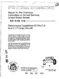
9 Objective. The project was carried out under the direction afG. A. Leonards and M. E. Harr. Major John T. Gaffey, II, developed theinstrumentation and obtained initial data on the static and dynamic frictioncoefficients on one sand for his PhD dissertation (l)*. William F. the experimental techniques and completed the study (includingtests on two sands) for his thesis (2). The report vas preparedby G. A. Leonards.* Numbers in parentheses refer to the References on page IIEDIP- TAL COXC??IL. GMRAL ~1 RTCZThe shearing force, F, required to initiate slip of on bndy on-mother divided by the force, N, betwen the contact surfacesis called the coeffie-ent of friction, coefficient of friction betwen sands such co=nstructicn= as steel. and concrete (including the effects of frictionredwcing lin~ers) was measured to co~are values of it obtained ihenslip is initiated by a slowly applied friction force (in abaut fiveriAUtes) as opposed to one aplied very rapidly (in one rni ecand orless), hereafter referred to as statics and " tests, test set-up chosen for the study is showm sche atically inFiguree 1 (mechanical details are described u=der TItarxatus andProcedures").
10 It consisted of a cylinder of sand encased in a rubbermembrane with a rod located on izs axis. By evacuating the air frcm_the inside of the mebrane a nornal pressure was applied on the snd/.odinterface. The rod was then caused to slid relative to the s:-d by theapDlication of "static" or "dynamic" forces in an axial determine the coefficient of static friction, ps, defined as:F-S (1)s iwhereFs = static friction force on the slip surface, at slipNs = static normal force applied on the surface, at slip2 Iam3 -REACTIONRINGa. THE STATIC MODELoin REACTIONFd-N AN5~F (t) THE DYNAMIC MODELFIG. I SCHEMATIC DIAGRAM OFEXPERIMENTAL CONCEPT3F. was masured directly by weighing the quanitity of water added tothe loading fr- when ship was induced. N. was obtained indirectly;avidiary tests to be described later showed that Fs w-s equal to theccnfini g pressure (a) due to the vacua, times the area of thesaid/rod interface.