Transcription of AHL Series Pump - Autoclave
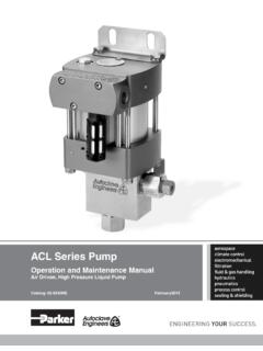
1 AHL Series PumpOperation and Maintenance ManualAir Driven, High Pressure Liquid PumpCatalog: 02-9242ME August 20142 Parker Autoclave EngineersInstrumentation Products DivisionErie, PA | Cat. 02-9242 MEModel # Serial # Drawing # Order # Mfg. Date Table of ConTenTs page Introduction .. 3 Meaning of Safety Words .. 3 Product Specification .. 3 Unpacking .. 3 Tools .. 3 Installation .. 3 Compressed Air Supply .. 4 Liquid Section .. 4 Pump Start-Up .. 5 Process Media .. 5 Pump Functionality .. 6 Suggested Maintenance .. 6 Trouble Shooting-Pneumatic Section .. 7 Trouble Shooting-High Pressure Liquid Section .. 8 Service .. 8 3 Parker Autoclave EngineersInstrumentation Products DivisionErie, PA | Cat.
2 02-9242 MESection Parker Autoclave Engineers pump discussed in this manual is operated using compressed air up to 110 psi ( bar) max, however maximum inlet air pressure is limited by the maximum liquid output pressure. Autoclave Engineers AHL Series pumps are used for pumping oil, water, and oil/water mixtures. Special seals are also available for chemical service. Please contact Parker Autoclave Engineers to discuss availability of special seals. The pump operates using a pressure ratio of the air piston surface area to the liquid plunger surface area.(Output liquid pressure = actual pump pressure ratio x input air pressure). Refer to the product literature for each pump model's actual air pressure of Safety WordsA safety related message is identified by a safety alert symbol and a signal word to indicate the level of risk involved with a particular hazard.
3 The definitions of the three signal words are as follows:indicates a potentially hazardous situation which, if not avoided, could result in death or serious a potentially hazardous situation which, if not avoided, may result in minor or moderate notes intended to bring attention to procedures that must be followed to ensure proper installation and performance will be placed in a box labeled SpecificationSee assembly drawing for product specifications:- Pump Geometry- Pump Materials of Construction- Maximum Allowable Working Pressure- Maximum Working Temperature- Pressure Ratio- Displacement- Repair Kit Part Numbers- Torque Information- WeightsWARNING!CAUTION!Section pump has been assembled and pressure tested at Parker Autoclave Engineers and is ready to be put into service.
4 The shipping carton should be opened and the contents carefully examined upon receipt from the carrier. Make sure there is no obvious damage to the contents. DO NOT use the equipment if any damage is evident. If damage has occurred, file a claim with the shipper before contacting Parker Autoclave Engineers Service all material within the container and check against the packing list to be sure all items are accounted for and are not damaged. Verify that the equipment model number supplied agrees with what was minimum, the tools required for installation of the pump in-clude a torque wrench, an open end wrench adapter (crows foot adapter) and an open end adjustable to the Tools, Maintenance and Installation Manual provided with the Data Book for information on torque wrenches and torque values for Parker Autoclave Engineers tubing and The pump will attach to the mounting location using (4) 7/16" bolts.
5 There are 4 holes provided on each pump for read this manual in its entirety before attempting to operate an Parker Autoclave Engineers high pressure liquid pump!WARNINGI nstallation to be performed only by properly trained individuals.!WARNINGP roper protective safety gear must be worn while installing and operating the pump.!WARNING4 Parker Autoclave EngineersInstrumentation Products DivisionErie, PA | Cat. 02-9242 MESection Air SupplyThe main air drive connection port on the pump is a female 1 FNPT and is located in the spool base housing. An additional female 1/8 FNPT air pilot valve connection port is located in the middle plate at the opposite side of the 1 NPT air inlet. This pilot connection must be plumbed to an unregulated and filtered air source. The purpose of this connection is to aid in low pres-sure differential start-up and restart of the pump while providing a more accurate pressure control.
6 The pump will not function if this unregulated air supply is not connected to the pilot valve supply air line filter with a minimum 5 microns filtration rating must be used on the supply line. If the air supply is not dry, a mist separator must be used to remove moisture in the air Autoclave Engineers can supply a complete air control package that includes a filter, air pressure regulator, air pres-sure gage and shutoff valve. Mist separators are also available. Contact the factory for more details on these bolt the pump to a substantially solid surface using the slotted holes provided.!WARNINGAHL pumps have a maximum sound level of 90 dBA. Wear hearing protection while working with or near the pump.!CAUTIONU nless otherwise noted, all air line accessories for the pump air drive should have, at minimum, a 1/2" FNPT connection.
7 The tubing/piping used to connect the components should have the maximum ID the pressure rating will allow. Reduc-ing the size before the air inlet will reduce air pressure flow and reduce flow rate of the use of an air line lubricator is not required and is not recommended. The oil in the air lubricator will cause the factory installed grease to be purged from the pump. Once an air lubricator is used the pump can never again be oper-ated without an air pump is designed to function from 20 psi to 110 psi ( to bar) air input pressure, however maximum inlet air pressure is limited by the maximum liquid output SectionAll AHL Series pumps have high pressure liquid outlet ports lo-cated on the side of the pump head s. The suction inlet ports on all AHL Series pumps are positioned opposite of the inlet checks.
8 Inlet: A liquid filter with at least a 100 mesh size must be installed before the suction port inlet to prevent damage to the check valves and high pressure seals due to debris. Refer to product literature for inlet connection details for each pump. The tubing or piping should be made from a corrosion resistant material and sized with a maximum ID to fit the inlet pipe : The outlet tubing ID must, at minimum, match the same size of the pump check valve gland port. Refer to product litera-ture for outlet connections details for each pump. Reducing out-let tubing or connection will reduce output liquid flow high pressure tubing must be rated to at least the maximum pump output pressure.!WARNINGV erify liquid pressure system is protected with an over pressure relief device.!WARNINGR estricting flow at the liquid inlet will cause problems with check valve performance and reduce output best performance, a liquid supply reservoir should be located higher than the inlet gland on the pump to create a small pressure head.
9 Be sure to make an air tight seal between the reservoir and the pump inlet connection. The connections between the reservoir and pump inlet should not be reduced from the FNPT connection order for the pump to flow properly, both outlets must be plumbed together into a tee to one single Autoclave EngineersInstrumentation Products DivisionErie, PA | Cat. 02-9242 MEIncrease the air pressure using the air pressure regulator until you achieve your desired output liquid pressure. At this point the pump will stall. You can calculate the output pressure by multiplying the input air supply by the actual pressure ratio of the pump. The pump will automatically restart if there is a drop in downstream high MediaParker Autoclave Engineers pumps discussed in this manual are used for pumping oil, water and oil/water mixtures.
10 Special seals are also available for chemical service. Please contact Parker Autoclave Engineers to discuss availability of special Start-UpFig. Air Line Schematic As shown above, a filtered main air supply line is required. The air line then must be split through a tee. One line will attach to the 1/8 FNPT pilot valve connection in the middle plate of the pump. The air pressure on this connection must be higher than the regulated main air supply on the air drive section. The sec-ond line out of the tee will go to a pressure regulator which can be set to achieve the desired output liquid pressure according to the pressure ratio of the pumps unique design allows for self priming. To prime, regulate the air pressure to between 5-15 psi or use an air flow regulator to reduce to a slow stroke frequency.
