Transcription of AIC+ Advanced Interface Converter - Rockwell …
1 AIC+ Advanced Interface Converter Catalog Number 1761-NET-AICUser ManualImportant User InformationSolid state equipment has operational characteristics differing from those of electromechanical equipment. Safety Guidelines for the Application, Installation and Maintenance of Solid State Controls (publication available from your local Rockwell Automation sales office or online at ) describes some important differences between solid state equipment and hard-wired electromechanical devices. Because of this difference, and also because of the wide variety of uses for solid state equipment, all persons responsible for applying this equipment must satisfy themselves that each intended application of this equipment is no event will Rockwell Automation, Inc. be responsible or liable for indirect or consequential damages resulting from the use or application of this examples and diagrams in this manual are included solely for illustrative purposes. Because of the many variables and requirements associated with any particular installation, Rockwell Automation, Inc.
2 Cannot assume responsibility or liability for actual use based on the examples and patent liability is assumed by Rockwell Automation, Inc. with respect to use of information, circuits, equipment, or software described in this of the contents of this manual, in whole or in part, without written permission of Rockwell Automation, Inc., is this manual, when necessary, we use notes to make you aware of safety , PLC, SLC, MicroLogix, PanelView, DTAM, and Rockwell Automation are trademarks of Rockwell Automation, not belonging to Rockwell Automation are property of their respective information about practices or circumstances that can cause an explosion in a hazardous environment, which may lead to personal injury or death, property damage, or economic information that is critical for successful application and understanding of the information about practices or circumstances that can lead to personal injury or death, property damage, or economic loss.
3 Attentions help you identify a hazard, avoid a hazard, and recognize the consequenceSHOCK HAZARDL abels may be located on or inside the equipment, for example, a drive or motor, to alert people that dangerous voltage may be HAZARDL abels may be located on or inside the equipment, for example, a drive or motor, to alert people that surfaces may be at dangerous 1761-UM004B-EN-P - June 2006 Summary of ChangesThe information below summarizes the changes to this manual since the last help you find new and updated information in this release of the manual, we have included change bars as shown to the right of this publication list4 Ordering publications4 Processor/cable 1761-UM004B-EN-P - June 20064 Summary of ChangesiPublication 1761-UM004B-EN-P - June 2006 Table of ContentsPrefaceWho Should Use This Manual .. 3 Purpose of This Manual.. 3 Additional Resources .. 4 Conventions Used in This Manual .. 4 Chapter 1 Product OverviewDescription .. 5 Operation Modes.
4 6 Device Compatibility .. 6 Chapter 2 Installation and WiringCompliance to European Union Directives .. 9 EMC Directive .. 9 Low Voltage Directive .. 9 Safety Considerations .. 10 Mount the AIC+ Advanced Interface Converter .. 11 Mount to a DIN Rail .. 11 Mount to a Panel .. 12 Wire the AIC+ Advanced Interface Converter .. 13 Wire the Power Supply .. 13 Wire to the Network Ports .. 14 Cable Choices .. 16 Recommended User-supplied Components .. 19 Chapter 3 Network ConnectionsNetwork Diagrams .. 21 Point-to-point Isolator .. 21 Components Replaced by the AIC+ Interface Converter . 22DH-485 Network with SLC 5/03 and SLC 5/04 Processors and a PC .. 23DH-485 Network with a MicroLogix 1000 Controller .. 24 Typical Three-node OEM Network .. 24 Networked Operator- Interface Device and MicroLogix Controller .. 25 Networks Using Ganged Converters .. 26 Network Extended to 2438 m (8000 ft) .. 27DF1 Master-slave Network with Modem.
5 28 Avoid Incorrect Connections .. 29 Chapter 4 Interpret the LED IndicatorsDiagnostics .. 31 Publication 1761-UM004B-EN-P - June 2006ii Table of ContentsAppendix ASpecifications and DimensionsGeneral Specifications .. 33 Hardware Handshaking .. 34 Auto Transmit Delay (turnaround time) per Communication Rate .. 35 Mounting Template .. 36 Index3 Publication 1761-UM004B-EN-P - June 2006 PrefaceRead this preface to familiarize yourself with the rest of the manual. This preface covers the following topics. Who should use this manual Purpose of this manual Conventions used in this manualWho Should Use This ManualUse this manual if you are responsible for designing, installing, programming, or troubleshooting control systems that use Allen-Bradley Small Logic controllers. You should have a basic understanding of SLC 500 and MicroLogix products and be able to interpret the ladder-logic instructions required to control your application. If you do not, contact your local Allen-Bradley representative for information on available training courses before using this product.
6 Purpose of This ManualThis manual is a reference guide for the Advanced Interface Converter (AIC+). This manual: gives you an overview of the AIC+ Interface Converter operation. explains the procedures to install and wire the AIC+ Interface 1761-UM004B-EN-P - June 20064 PrefaceAdditional ResourcesThe following documents contain additional information regarding Rockwell Automation DocumentationIf you would like a manual, you can: download a free electronic version from the Internet at purchase a printed manual by contacting your local distributor or Rockwell Automation Used in This ManualThe following conventions are used throughout this manual. Bulleted lists, such as this one, provide information, not procedural steps. Numbered lists provide sequential steps or hierarchical information. Bold type is used for emphasisForRead This DocumentDocument NumberA guide to understanding and selecting SLC 500 productsSLC 500 System Selection Guide1747-SG001A description on how to install and use your modular SLC 500 programmable controllerUser Manual for Modular Hardware Style Programmable Controllers1747-UM011A description on how to install and use your MicroLogix 1000 programmable controllerMicroLogix 1000 Programmable Controller User Manual1761-UM003A description on how to install and use your MicroLogix 1200 programmable controllerMicroLogix 1200 Programmable Controller User Manual1762-UM001A description on how to install and use your MicroLogix 1100 programmable controllerMicroLogix 1100 Programmable Controller User Manual1763-UM001A description on how to install and use your MicroLogix 1500 programmable controllerMicroLogix 1500 Programmable Controller User Manual1764-UM001A guide to DF1 protocolData Highway/Data Highway Plus/Data Highway
7 II/Data Highway-485 Cable1770-UM022A guide to wiring and grounding guidelinesIndustrial Automation Wiring and Grounding Guidelines1770-IN041A glossary of industrial automation terms and abbreviationsAllen-Bradley Industrial Automation 1761-UM004B-EN-P - June 2006 Chapter 1 Product OverviewDescriptionThe AIC+ Advanced Interface Converter provides a communication link between various networked devices. The AIC+ Interface Converter is compatible with a variety of SLC and MicroLogix controllers and Port and Switch LocationsMicroLogix 1000, 1200, and 1500 controllers provide power to the AIC+ Interface Converter via the RS-232 8-pin mini-DIN port s cable. However, if a MicroLogix controller is not connected to this port, a 24V dc power supply connected to the Converter s external power terminals is required. The dc power-source selector switch needs to be set for your particular configuration. See Network Diagrams starting on page 21 for more details on how to wire and configure the AIC+ Interface Converter .
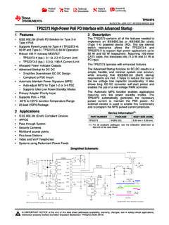
8 RS-485 Communication Port (Phoenix Plug)RS-232 (DB-9, DTE) Communication PortRS-232 (8-pin mini-DIN) Communication PortCommunication-rate Selector SwitchTerminals for external 24V dc power supply and chassis Power-source Selector SwitchPublication 1761-UM004B-EN-P - June 20066 Product OverviewThe communication-rate selector switch is used to match the communication rate filter of the AIC+ Interface Converter to the network communication rate. This switch does not change the network communication rate and is normally left in the AUTO position. In high noise environments, the communication-rate selector switch should be taken out of the AUTO mode and set to the same communication rate as the network. See Auto Transmit Delay on page 35 for more information on communication rates. Operation Modes The AIC+ Interface Converter can be used in the following modes. Point-to-point isolator RS-232 to RS-485 isolator RS-232 to half-duplex user mode ASCII isolatorCommunication is established using hardware handshaking or auto transmit signals.
9 Device CompatibilityThe AIC+ Interface Converter can be used to interconnect the following devices. SLC 500, 5/01, 5/02, and 5/03 processors (channel 1) SLC 5/03, 5/04, and 5/05 processors (channel 0) MicroLogix controllers Logix controllers 1756-DH485 ControlLogix module Operator Interface devices Personal computer serial ports (or any 9-pin DTE serial port) Modems TIPYou cannot connect the 1761-HHP-B30 Hand-held Programmer to the AIC+ Advanced Interface 1761-UM004B-EN-P - June 2006 Product Overview 7 Node Address Identification There is no node address associated with the network node address is configured in the device connected with this node address is configured in the device connected with this this area to mark the node address of each 1761-UM004B-EN-P - June 20068 Product Overview9 Publication 1761-UM004B-EN-P - June 2006 Chapter 2 Installation and WiringCompliance to European Union DirectivesIf this product has the CE mark it is approved for installation within the European Union and EEA regions.
10 It has been designed and tested to meet the following directives. EMC Directive This product is tested to meet Council Directive 89/336/EEC Electromagnetic Compatibility (EMC) and the following standards, in whole or in part, documented in a technical construction file. EN 50081-2 EMC Generic Emission Standard, Part 2 Industrial Environment EN 50082-2 EMC Generic Immunity Standard, Part 2 Industrial Environment This product is intended for use in an industrial environment. Low Voltage Directive This product is tested to meet Council Directive 73/23/EEC Low Voltage, by applying the safety requirements of EN 61131 2 Programmable Controllers, Part 2 Equipment Requirements and Tests. For specific information required by EN 61131-2, see the appropriate sections in this publication, as well as the Industrial Automation Wiring and Grounding Guidelines, publication 1761-UM004B-EN-P - June 200610 Installation and WiringSafety ConsiderationsThis equipment is suitable for use in Class I, Division 2, Groups A, B, C, D, or nonhazardous locations only.