Transcription of AIM™ in a VIA™ Package - Vicor
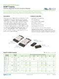
1 AIM in a VIA Package Rev 1 of 14 09/2018 AIM in a VIA PackageUniversal AC Input ModuleAIM1714xB6MC7D5yzzFeatures & Benefits Universal input (85 264 VAC, 47 63Hz) Chassis-mount or PCB-mount form factor Small robust Package Low profile EMI filtering Meets EN61000-4-5 Class 3 surge protection when used with external MOV and fuse, paired with Vicor PFM4414 productsTypical Applications Small cell base stations Telecom switching equipment LED lighting Test and Measurement Equipment 200 400W Industrial Power Systems Office EquipmentProduct DescriptionThe AIM in a VIA Package (AC Input Module) is a front-end module designed to interface directly with worldwide AC mains and provide a rectified AC input to the Vicor family of PFM4414 VIA products.
2 The AIM combines a bridge rectifier, EMI filter and surge protection circuitry in an easy-to-use VIA plastic housing. The AIM and PFM components in a VIA Package can realize a small, efficient and simple AC-DC solution for a broad range of end x x [ x x ]Part Ordering InformationProductFunctionPackage LengthPackageWidthPackageTypeInput VoltageRange RatioOutput Voltage (Range)Max Output PowerProduct GradeOption FieldAIM1714xB6MC7D5yzzAIM =AC Input ModuleLength in Inches x 10 Width in Inches x 10B = Board VIAV = Chassis VIAI nternal ReferenceC = 20 to 100 CT = 40 to 100 C00 = Chassis/Always On04 = Short Pin/Always On08 = Long Pin/Always OnProduct RatingsVIN = 85 264 VPOUT = up to 450 WVOUT = Rectified ACIOUT = in a VIA Package Rev 2 of 14 09/2018 AIM1714xB6MC7D5yzz 24 V 10 A V 10 V 8 A Cool-Power ZVS Buck2 x Cool-Power ZVS Buck+_+_+_PFM +IN IN+OUT OUT24 V+++C1C2C3M1J185 264 VACI nlet+OUT OUTAIMM2F1 LNMOVT ypical PCB Mount ApplicationsThe PCB terminal option allows mounting on
3 An industry standard printed circuit board, with two different pin lengths. Parts List for Typical PCB Mount ApplicationsJ1 Qualtek 703W IEC 320-C14 Power InletF1 Littelfuse 8A 250 VAC 5 x 20mm holderM1 Vicor AIM AIM1714BB6MC7D5yzzM2 Vicor PFM PFM4414BB6M24D0yzz or Vicor PFM PFM4414BB6M48D0yzzC1, C2, (C3)Select capacitors based on 4414 VIA PFM model used, as per typical application parts TMOV20RP300E VARISTOR 10kA 30V 250 J 20mm AIM in a VIA Package Rev 3 of 14 09/2018 AIM1714xB6MC7D5yzzPFM +IN IN+OUT OUTFanRelaysCoin BoxControllerDispensors24V1688C1C2C3J185 264 VACI nletM1 AIMF1M2+OUT OUTLNMOVT ypical Chassis Mount ApplicationsThe AIM and PFM are available in chassis-mount option, saving the cost of a PCB and allowing access to both sides of the power supply for cooling.
4 The parts list below minimizes the number of interconnects required between necessary components, and selects components with terminals traditionally used for point-to-point chassis List for Typical Chassis Mount ApplicationsJ1 Qualtek 719W or 723W IEC 320-C14 Power InletF1 Littelfuse 8A 250 VAC 5 x 20mm in a J1, or separate fuse holderM1 Vicor AIM AIM1714VB6MC7D5y00M2 Vicor PFM PFM4414VB6M24D0y00 or Vicor PFM PFM4414VB6M48D0y00C1, C2, C3 Select capacitors based on PFM4414 VIA model used, as per typical application parts TMOV20RP300E VARISTOR 10kA 300V 250 J 20mm AIM in a VIA Package Rev 4 of 14 09/2018 AIM1714xB6MC7D5yzzN+OUTTOP VIEWAIM1714 VIA - Chassis Mount - Terminals UpL OUTTOP VIEWAIM1714 VIA - PCB Mount - Pins DownL OUTN+OUTPin ConfigurationPin DescriptionsSignal NameTypeFunctionNINPUT POWER RETURNAC Neutral / Line 2 inputLINPUT POWERAC Line 1 input OUTOUTPUT POWER RETURNN egative output power terminal+OUTOUTPUT POWERP ositive output power terminalPlease note that these pin drawings are not to in a VIA Package Rev 5 of 14 09/2018 AIM1714xB6MC7D5yzzAbsolute Maximum RatingsThe absolute
5 Maximum ratings below are stress ratings only. Operation at or beyond these maximum ratings can cause permanent damage to the Voltage at Input Terminals, 1ms Max0600 VPKI nput Voltage (AC RMS) Continuous0275 VRMSO utput Current (Continuous) Internal Temperature 40125 CStorage Temperature 65125 CInput / Output Pin Torque and Mounting Torque4 [ ] [ ]AIM in a VIA Package Rev 6 of 14 09/2018 AIM1714xB6MC7D5yzzElectrical SpecificationsSpecifications apply over all line and load conditions, 50Hz and 60Hz line frequencies, TC = 25 C, unless otherwise noted. Boldface specifications apply over the temperature range of the specified product grade.
6 AttributeSymbolConditions / NotesMinTypMaxUnitInput SpecificationInput Voltage Range, Continuous OperationVIN85264 VRMSI nput Voltage Range, Transient, Non-Operational (Peak), 30s Minimum IntervalVIN600 VSource Line Frequency Rangefline4763 HzPower FactorPFPlease see PFM in VIA Package datasheet for power SpecificationOutput PowerPOUT450 WOutput Current (Continuous) in a VIA Package Rev 7 of 14 09/2018 AIM1714xB6MC7D5yzzACINPUTOUTPUTTO PFMMOVMOVSERIESSWITCHCM FILTERRECTIFIERB lock DiagramApplication Characteristics150 kHz30 MHzSGL1 MAUnitdBV Trd55022 REDResBW 9 kHzMeas T 20 msDetMAAtt 20 dBINPUT 2015 08:291 MHz10 MHz 30 40 50 60 70 80 90 20 1001 Marker 1 [T1] dBV kHz1 [T1] dBV kHz22 QPA22 QPBDate: 08:29:08 Figure 1 Typical conducted emissions, peak scan, with PFM4414 VIA, 115V, 90% load with PFM OUT connected to GND150 kHz30 MHzSGL1 MAUnitdBV 2015 08:58 ResBW 9 kHzMeas T 20 msDetMAAtt 20 dBINPUT 21 MHz10 MHz 30 40 50 60 70 80 90 20 1001 Marker 1 [T1] dBV kHz1 [T1] dBV kHz22 QPA22 QPBDate: 08:58.
7 24 Figure 2 Typical conducted emissions, peak scan, with PFM4414 VIA, 230V, 90% load with PFM OUT connected to GNDE fficiency (%) Load Current (A)85 V 115 VVIN:EffP DISS85 V 115 VPower Dissipation (W)99%98%97%96% 3 VIN to VOUT efficiency and power dissipation vs. VIN and IOUT, TCASE = 20 CAIM in a VIA Package Rev 8 of 14 09/2018 AIM1714xB6MC7D5yzzGeneral CharacteristicsSpecifications apply over all line and load conditions, 50Hz and 60Hz line frequencies, TC = 25 C, unless otherwise noted. Boldface specifications apply over the temperature range of the specified Product / [ ]mm [in] [ ]mm [in] [ ]mm [in]VolumeVolWithout [ ]cm3 [in3]Mass (Weight)M35 [ ]g [oz]Pin MaterialC145 copper, half hardUnderplateLow-stress ductile nickel50100 inPin inSoft inThermalOperating Case TemperatureTCC-Grade 20100 CT-Grade 40100 CThermal Resistance, Internal to Case Non-Pin Side INT_NON_PIN_SIDEE stimated thermal resistance to maximum temperature internal component from isothermal non-pin/non-terminal C/WThermal DesignSee Thermal Considerations on Page 10 SolderingTemperatureSee: AN.
8 401 PCB Mount VIA Soldering GuidelinesReliabilityMTBFMIL-HDBK-217FN2 Parts Count - 25 C Ground Benign, Stationary, Indoors / Issue 2 - Method I Case III; 25 - 25 C Ground Benign, Stationary, Indoors / Approvals / StandardsEN60950-1; CE marked for low voltage directive and RoHS recast directive, as applicableDielectric Withstand (Hipot)IN / OUT to Case1500 VACL eakage Current / Touch CurrentNo Y capacitor connection of GND connection within packageNegligibleEMI/EMC ComplianceFCC Part 15, EN55022, CISPR22: 2006 + A1: 2007, Conducted EmissionsClass B Limits - with PFM4414 VIA OUT connected to GNDEN61000-4-5: 2006, Surge ImmunityLevel 3, Immunity Criteria A with PFM in a VIA Package with external TMOV and fuse, shown on page 2 or 3, in a VIA Package Rev 9 of 14 09/2018 AIM1714xB6MC7D5yzzEnvironmental QualificationTesting ActivityReference StandardTest DetailsHigh Temperature Operating Bias/Life (HTOB/HTOL)JESD22-A108D1000hrs.
9 Nominal Full Load at Max operating temperatureTemperature Cycling Test (TCT)IPC-9592B125 C to 40 C, 700 cyclesTemperature Humidity Bias (THB)JESD22-A101C1000hrs. Nominal Input voltage, Minimal load 85 C, 85% RHHigh Temperature Storage (HTS)JESD22-A103D1000hrs. 125 CLow Temperature Storage (LTS)JESD22 A1191000hrs. 65 CRandom VibrationMIL-STD-810 GMethod , Procedure I, Category 24, 20-2000Hz, 1hour /axis for 3 axis. Product mounted on an evaluation board, nominal line 50% ShockMIL-STD-810 GMethod , Procedure I, Functional shock 40G, total of 18 shocks. Product mounted on an evaluation board, nominal Line 50% Accelerated Life Test (HALT)Internal Vicor Procedure - DP-0265 Low and high temperature tests, rapid thermal cycling, random vibration testing, combined stress testing and destruct SolventsMIL-STD-202 GMethod 215K, 3 minutes exposureESD Human Body ModelJEDEC JS-001-2012 Class 1C (HBM) MinimumESD Charged Device ModelJESD22-C101 EClass II (CDM)
10 MinimumAIM in a VIA Package Rev 10 of 14 09/2018 AIM1714xB6MC7D5yzzThermal ConsiderationsThe AIM in a VIA Package can be cooled using single-side cooling from the non-pin side. Since the AIM has a maximum internal temperature rating, it is necessary to estimate this internal temperature based on a system-level thermal solution. To this purpose, it is helpful to simplify the thermal solution into a roughly equivalent circuit where power dissipation is modeled as a current source, isothermal surface temperatures are represented as voltages sources, and thermal resistances are represented as resistors.