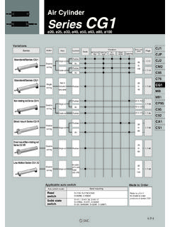
Transcription of Air Cylinder Series CG1 - SMC Pneumatics
1 1-7-1CJ1 CJPCJ2CM2C85C76CG1 MBMB1CP95C95C92CA1CS1 Air CylinderSeries CG1 20, 25, 32, 40, 50, 63, 80, Variations SeriesStandard/ Series CG1 Standard/ Series CG1 Non-rotating rod Series CG1 KDirect mount Series CG1 RDirect mount/Non-rotating rod Series CG1 KRLow friction Series CG1 QActionDoubleactingSingleactingDoubleact ingDoubleactingDoubleactingDoubleactingR odSingle rodDouble rodSingle rod(Spring return/Spring extend)Single rodDouble rodSingle rodCushionRubberAirRubberAirRubberRubber AirRubberRubberAirRubberSingle rodSingle rodNo cushion( 20 to 63)Rubber ( 80, 100)BasicVariationWith One-touchfittingWith rodbootAir- hydro CleanseriesCopper freeBore size(mm)20to10020to4020 to 6340 to 6320 to 6320to6320to6320to100 Refer to for made to order products of Series CG1 Applicable auto switchAuto switch modelReed switchSolid state switchBand mountingD-C7/8, D-C73C/C80CD-B5/B6, D-B59WD-H7 , D-H7 W, D-H7 FD-H7 BAL, D-H7C, D-G5/K5D-G5 W/K59W, D-G59F, D-G5 NTLMade to OrderWith auto switchStandardCDG1L25 LNN25 With auto switch (magnet)
2 20253240506380100 Bore size20mm25mm32mm40mm50mm63mm80mm100mmCyl inder stroke (mm)CG1 BasicAxial footFront flangeRear flangeFront trunnionRear trunnionClevisMountingBLFG U T D100100 Refer to for Standard Stroke Table. JKRod boot (at one side)Without rod bootNylon tarpaulin Heat resistant tarpaulin Not available for bore sizes 80 and 100. Mounting brackets are included, not mounted. Foot brackets and front flanges are fitted when rod boots are mounted. CushionNARubber bumper Air cushionStyle Special functionWiring(Output)3 wire(NPN)2 wire24V5V12V5V, 12V12V5V, 12V5V, 12V12V5V, 12V12V5V, 12V C76C73C80C73CC80CH7A1H7A2H7BH7CH7 NWH7 PWH7 BWH7 BAH7 NFH7LF100V100V or less24V or less24 VLoad voltage3 wire (NPN)3 wire (PNP)2 wire2 wire3 wire (NPN)3 wire (PNP)3 wire (NPN)4 wire(NPN)IndicatorElectricalentryAuto switch modelApplicable bore size 20 to 63 20 to 100B53B54B64B59WG59G5PK59G59WG5 PWK59WG5 BAG5 NTG59 FApplicableloadGrommetGrommetGrommetDiag nostic indication (2 color)Diagnostic indication(2 color)
3 Water resistant (2 color)With timerDiagnostic output (2 color)Latch with diagnostic output(2 color)Applicable Auto Switches/Refer to for further information on auto switchSolid state switchConnectorConnectorGrommetYesYesNoY esNoNoYesYesDCACLead wire (m) ( )3(L)5(Z)None(N)ICRelayPLCR elayPLCPLC200 Vor lessICICICIC Lead wire length ) C73C 5m Z ) C73CZ 3m L C73CL None N C73CN Solid state switches marked with " " are manufactured upon receipt of B53 Number of auto switches Sn21n Without auto switch(Built-in magnet)Auto switch Refer to the table below for selecting applicable auto : Double Acting Single RodSeries CG1 20, 25, 32, 40, 50, 63, 80, 100 How to Order1-7-2CJ1 CJPCJ2CM2C85C76CG1 MBMB1CP95C95C92CA1CS1 Front/Rear trunnion styles are not available for bore sizes 80 and size (mm)ActionLubricationFluidProof pressureMax.
4 Operating pressureMin. operating pressureAmbient and fluid temperaturePiston speedStroke toleranceThread toleranceCushionMounting Double acting/Single Without auto switch: 10 to +70 C (No freezing)With auto switch: 10 to +60 C (No freezing)JIS class 2 Rubber bumper/Air cushion+ , Axial foot, Front flange, Rear flange, Front trunnion, Rear trunnion, Clevis (Used for changing the port location by 90 degrees.) Pivot bracket is not available for bore sizes 80 and 100. Pins and snap rings for double knuckle joint are included, not end nutClevis pinSingle knuckle jointDouble knuckle joint (With pins)Pivot bracketRod bootBasic AxialfootFrontflangeRearflangeFronttrunn ionReartrunnionClevisNote 1) Other intermediate strokes can be manufactured upon receipt of are not used for the intermediate strokes.
5 Refer to to for 2) Long stroke applies to the axial footand the front flange style. If othermounting brackets are used or the length exceeds the stroke limit,the stroke should be determined based on the stroke selection tablein the technical size(mm)2025324050/6380100 Standard stroke (1)(mm)25, 50, 75, 100, 125, 150, 20025, 50, 75, 100, 125, 150, 200, 250, 300 Longstroke (2)(mm)Maxstroke(mm)201 to 350301 to 400301 to 450301 to 800301 to 1200301 to 1400301 to 15001500 Maximum ambient temperature for the rod boot only. Rod Boot MaterialsSymbolJKMaterialNylon tarpaulinHeat resistant tarpaulinMax.
6 Operating temp70 C00110 C Minimum Strokes for Auto Switch MountingAuto switch model215mm20mm20mm110mm15mm10mmD-C7/C8D- B5/B6D-H7D-G5/K5D-B59WD-H7 LFNumber of switches 50 to 1000mm/sUp to 1000 mm, Up to 1200 mm2025324050638010050 to 700mm/sUp to 1000 mmUp to 1500 mmJIS symbolDouble actingStandard strokeMade to OrderRefer to for made to order products of Series BracketSubstantially shorter length: 20 to 40: 15 to 30mm(in comparison with CM2 Series ) 40 to 63: 17 to 28mm(in comparison with CA1 Series ) 80 to 100: 9 to 33mm(in comparison with CA1 Series )High speed operation: 1000mm/s( 80 and 100 operate at 700mm/s)Provided with an air cushion asstandardTwo cushions are available:an air cushion or rubber bumperWeight reduction of 10 to 50%(50mm stroke, in-house comparison)Highly accurate mountingbrackets(Axial foot, front flange)Refer to for part numbers for the mounting Switch Mounting BandRefer to for part numbers for the mounting bands.
7 + + + : Double Acting Single Rod Series CG11-7-31-7-4 Order two foot brackets per a Cylinder . Clevis pins, snap rings and mounting bolts are attached for the clevis. Mounting bolts are attached for the foot type and the flange Bracket Part No. Axial foot FlangeTrunnionClevis Pivot bracketMounting bracketBore size (mm)20CG-L020CG-F020CG-T020CG-D020CG-020 -24A25CG-L025CG-F025CG-T025CG-D025CG-025 -24A32CG-L032CG-F032CG-T032CG-D032CG-032 -24A40CG-L040CG-F040CG-T040CG-D040CG-040 -24A50CG-L050CG-F050CG-T050CG-D050CG-050 -24A63CG-L063CG-F063CG-T063CG-D063CG-063 -24A80CG-L080CG-F080 CG-D080CG-080-24A100CG-L100CG-F100 CG-D100CG-100-24 AAuto Switch Mounting Bracket Part No.
8 Auto switchmodelD-C7/C8D-H7D-B5/B6D-G5/K5 Bore size (mm)20 BMA2-020BA-0125 BMA2-025BA-0232 BMA2-032BA-3240 BMA2-040BA-0450 BMA2-050BA-0563 BMA2-063BA-0680 BA-08100 BA-10 Weight(kg)Bore size (mm)Basic weightBasicAxial footFlangeTrunnionClevisPivot bracketSingle knuckle joint Double knuckle joint (with pins)Additional weight by each 50 strokeAdditional weight by air cushion Additional weight by long A set of following stainless steel mounting screws is attached. (A switch mounting band is not attached. Please order the band separately.) BBA3: D-B5/B6/G5 types BBA4: D-C7/C8/H7 types "D-G5 BAL" and "D-H7 BAL"switches are set on the Cylinder with the screws above when shipped.
9 When a switch only is shipped, BBA3 or "BBA4" screws are example: CG1LA20-100 (Foot, 20, 100 stroke) Basic weight (Foot, 20) Additional weight stroke Cylinder stroke 100 stroke Additional weight by air cushion + X 100/50+ CG1 ClevisFollow the procedures below when mounting apivot bracket on the the procedures below when mounting apivot bracket on the trunnion. 20 to 63 20 to 63 80, 100 Mounting Procedures CJ1 CJPCJ2CM2C85C76CG1 MBMB1CP95C95C92CA1CS1 Built-in One-touch FittingMountingCG1 FNBuilt-in One-touch fittingA style in which One-touch fittings are built into the Cylinder .
10 It dramatically reduces the piping labour and installation operating pressureMin. operating pressurePiston speedCushionMountingSpecificationsApplic able Tube size (mm) 20, 25, 32, 40, 50, 63 Double acting/Single to 750mm/s Rubber bumper Auto switch can be , Axial foot, Front flange, Rear flange, Front trunnion, Rear trunnion, Clevis(Used for changing the port location by 90 degrees.)Bore size (mm)Applicable tube (mm)Applicable tube material 20 6/4 25 6/4 32 6/4 40 8/6 50 10 63 10 , Soft nylon, Polyurethane Refer to for other SeriesStroke10-CG1 NClean Series (with relief port)The rod portion of the actuator has a double seal construction, and a relief port is provided to discharge the exhaust air directly outside of the clean room.