Transcription of Aircraft Components and Subsystems
1 1 Aircraft Components and Subsystems This chapter deals with the fundamental physical Components and properties of con-ventional fixed-wing Aircraft . This material is covered in detail in many textbooks (seeAnderson [1998, 2000], Asselin [1997], Eshelby [2000], Layton [1988], Lowry [1999],Mair and Birdsall [1996], Roskam and Lan [1997], Saarias [2006], Shevell [1988],Torenbeek and Wittenberg [2009], and Yechout and Bossert [2003]); see Collinson (1996)for an overview that also describes flight instruments and avionics. The treatment here isbrief and emphasis is given to the aspects of conventional Aircraft that are most related totheir flight Aircraft Subsystems for ConventionalFixed-Wing AircraftFigure illustrates a conventional fixed-wing Aircraft that is the basic flight vehicle ofinterest in this book.
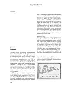
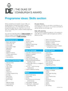
2 The key physical Components , or Subsystems , that define the aircraftare the fuselage, the wings, the horizontal tail, the vertical tail, and the propulsion fuselage provides working volume for passengers, cargo, and Aircraft Subsystems thatare internal to the Aircraft . The fuselage is important in terms of achieving particular flightmissions, but it is not especially important from a flight performance perspective. Thetwo wings are crucial for flight, since their main purpose is to generate lift. The aircraftillustrated in Figure , and all Aircraft considered hereafter, are fixed-wing Aircraft , sincethe wings are rigidly attached to the fuselage. This is in contrast with helicopters or otherrotary wing flight vehicles that generate lift using rotating important flight Subsystems , illustrated in Figure , are the horizontal tail,the vertical tail, and the engines.
3 The horizontal and vertical tails are rigidly attached tothe fuselage as indicated. The horizontal tail provides longitudinal stability and controlcapability, while the vertical tail provides directional stability and control capability. Theengines are crucial flight Subsystems , since they generate the thrust force that acts on theaircraft. Note that gliding flight, studied in chapter 6, occurs if the engines are turned offso that they do not generate thrust; gliders have no propulsion above descriptions imply that the Aircraft can be viewed as a rigid body, and thisis the perspective that is taken throughout. That is, there is no relative motion between thephysical Aircraft Subsystems such as the fuselage, the wings, and the vertical and horizontalCopyrighted Material2 Chapter 1 Fuselage:provides volumeWings:generate liftEngines:produce thrustVertical tail:provides directionalstability and controlHorizontal tail:provides longitudinalstability and controlFigure Since many forces act on these physical Subsystems , the rigid body assumption is onlya crude approximation.
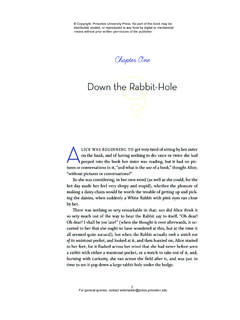
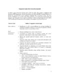
4 In fact, the Aircraft physical structures deform under the appliedforces that occur during flight. Issues of structural design and analysis are important toguarantee that the rigid body assumption is is the appropriate point to mention another important assumption that holdsthroughout the analysis presented subsequently. The complete Aircraft , consisting of thefuselage, the wings, the horizontal and vertical tails, and all other flight Subsystems ,has a plane of mass symmetry that exactly bisects the Aircraft . This assumption isa consequence of the design of conventional fixed-wing Aircraft where, in particular,engines mounted on the fuselage or the wings are balanced to satisfy this mass aerodynamic Control SurfacesFigure illustrates three types of aerodynamic control surfaces: the elevator, the ailerons,and the rudder.
5 The elevator is one (or more than one) movable flap, located on thetrailing edge of the horizontal tail. Deflection of the elevator changes the air flow over thehorizontal tail in such a way that a pitch moment on the Aircraft is generated. The aileronsconsist of a pair of movable flaps, located on the trailing edge of each wing; ailerons usuallyoperate in differential mode so that if one flap is deflected up the other flap is deflecteddown by the same amount or vice versa. Differential deflection of the ailerons changes theair flow over the wings in such a way that a roll moment on the Aircraft is generated. Therudder is one (or more than one) movable flap, located on the trailing edge of the verticaltail.
6 Deflection of the rudder changes the air flow over the vertical tail in such a way that ayaw moment on the Aircraft is generated. The elevator deflection, rudder deflection, and thedifferential deflection of the ailerons are typically viewed as angles measured from somereference MaterialAircraft Components and Subsystems3 AileronRudderElevatorFigure control movable flaps are referred to as aerodynamic control surfaces; they generatemoments on the Aircraft according to the principles of aerodynamics. The precise meaningsof pitch, roll, and yaw moments are described later. These moments are used to maneuverand control the flight of the modern Aircraft have unconventional elevators, ailerons, and rudders, as well asadditional flaps on the fuselage referred to as canards.
7 Although many aerodynamic controlsurface designs are possible, they all are intended to generate pitch, roll, and yaw subsequent development in this book is based on the assumption that conventionalelevators, ailerons, and rudders are Aircraft Propulsion SystemsThe Aircraft engines, together with associated fuel tanks and related hardware, are referredto as propulsion systems. The purpose of the propulsion system is to generate a thrust forcethat propels the Aircraft in flight. Although engines and propulsion systems are extremelycomplicated, detailed knowledge of the engine specifications is not required to analyzeflight properties of an Aircraft . Rather, the key features for the study of steady flight arethe maximum thrust (or the maximum power) that the engine can produce and the rate atwhich fuel is burned to produce a given thrust level (or power level).
8 From the earliest days of powered flight, propulsion systems have consisted of aninternal combustion engine that causes rotation of a propeller. The blades of the propellerare designed so that they generate a thrust force. Such propulsion systems remainin common use today, especially for low-speed Aircraft for which cost and durabilityconsiderations are primary. The important specifications for this type of propulsion systemare the maximum power that the internal combustion engine can produce, the rate of fuelburned to provide a specified power level, and the efficiency of the important technological outcome of World War II was the development of jet enginetechnology. Such propulsion systems make high-speed flight possible.
9 Most jet enginesconsist of a compressor, a turbine, and a combustor that are used to accelerate the flow of airthrough the engine, thereby producing a thrust force on the Aircraft . These turbojet enginesare extremely complicated, but the important specifications are the maximum thrust thatCopyrighted Material4 Chapter 1the turbojet engine can produce and the rate of fuel burned to provide a specified engines use turbine and jet engine technologies to turn a propeller thatgenerates a thrust force on the Aircraft . These propulsion systems exhibit some of thefeatures of conventional jet engines, but the efficiency of the propeller is also , rocket engines have been used to generate propulsive thrust forces on certainexperimental Aircraft .
10 A rocket engine consists of fuel and an oxidizer that are storedinternally in the Aircraft ; as the fuel is burned the combustion products are exhausted outa nozzle to produce a thrust force on the Aircraft . rocket engines can generate extremelylarge levels of thrust, but they have limited duration of focus here is on conventional propulsion systems: either a propeller driven by aninternal combustion engine or a turbojet engine. Many of the subsequent developments canbe modified to handle other types of propulsion Aircraft propulsion system produces a thrust force vector that has a fixed directionwith respect to the Aircraft . This property arises since the engines are typically fixed in theaircraft, either on the wings or on the fuselage.