Transcription of Airflow quick reference guide - Fluke Corporation
1 Calculating Air Changes per HourACH = Q x 60 / Room Volume ft3 Q = ft3/minute (CFM)Calculating Air Velocity (Standard, 70 F @ in. Hg)V = 4005 x VPVP = (V/4005)2V = Velocity, fpmVP = Velocity pressure, in. wcCalculating Air Velocity with density correction (Actual)V = x VP/DV = Velocity, ft/minute (fpm)VP = Velocity pressure, in. wcD = Density, lbs/ft3, x (530/460+Tact) x (Pact / )Tact = measured dry bulb temperature of the actual airstream, FPact = absolute pressure of the actual airstream, in. HgCalculating Air Flow (Standard, 70 F @ in. Hg)Q = A x VQ = ft3/minute (CFM)A = duct area (ft2)V = Velocity, ft/minute (fpm)Calculating Air Flow with density correctionCorrecting for standard cfmSCFM = ACFM(530/(460+Tact))( )SCFM = standard flow rateACFM = actual flow rate= measured flow rateTact = measured dry bulb temperature of the actual airstream, FPact = absolute pressure of the actual airstream, in.
2 HgCorrecting for actual cfm ACFM = SCFM((460+Tact)/530)( )SCFM = standard flow rateACFM = actual flow rate = measured flow rateTact = measured dry bulb temperature of the actual airstream, FPact = absolute pressure of the actual airstream, in. HgCalculating % of Outside Air (%OA)% OA = (RAT - SAT) / (RAT - OAT) x 100 SAT = (%OA x OAT) + (%RA x RAT) / 100 OAT = (SAT x 100) - (%RA x RAT) / %OARAT = (SAT x 100) - (%OA x OAT) / %RARAT = Return Air TemperatureSAT = Supply Air Temperature (or mixed air temperature)OAT = Outside Air Temperature%RA = Percentage Return AirCalculating Duct PressureVP = TP-SPTP = VP+SPTP = total pressure, in. wc SP = static pressure, in. wc VP = velocity pressure, in. wcUsing Fan Laws to Assess Performance ChangesCFM2 = CFM1 x (RPM2 / RPM1)SP2 = SP1 x (CFM2/CFM1)2 BHP2 = BHP1 x (CFM2 / CFM1)3 CFM1 = Cubic feet minute (Existing)CFM2 = Cubic feet minute (New)SP1 = Static pressure (Existing)SP2 = Static pressure (New)BHP1 = Power consumed by propeller (Existing)BHP2 = Power consumed by propeller (New) Airflow quick reference DPerforming duct traversalsFor maximum Airflow accuracy, several readings must be taken across a traverse plane, converted to velocity, then averaged.
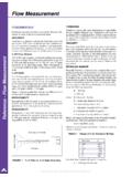
3 The illustration in Figure 1 shows the points along the traverse plane where measurements should be taken, either in rectangular or circular ducts. A minimum of 25 points must be measured in a rectangular duct traverse. When traversing a duct side less than 18 in. (450 mm), take readings from the center of equal areas that are no more than 6 in. (150 mm) apart, with a minimum of two points per side of the duct. The preferred location of the traverse in a supply duct should be in a straight section of duct with 10 straight duct diameters upstream, and 3 straight duct diameters downstream of the traverse plane, although a minimum of 5 duct diameters upstream and 1 duct diameter downstream may give adequate results.
4 When the traverse is located close to the fan, flow conditions are usually more favorable upstream on the return side. The traverse on the upstream side should be duct diameters upstream of the fan inlet. Equivalent diameter = (4HV/ ) H = horizontal duct dimension V = vertical duct dimension = maximum duct velocitiesApplicationMain Ducts*Branch DuctsSupply (fpm)Return (fpm)Supply (fpm)Return (fpm)Apartments1000800600600 Auditoriums130011001000800 Banks2000150016001200 Hospital Rooms1500130012001000 Hotel Rooms1500130012001000 Industrial3000180022001500 Libraries2000150016001200 Meeting Rooms2000150016001200 Offices2000150016001200 Residences1000800600600 Restaurants2000150016001200 Retail Stores2000150016001200 Theaters130011001000800*Use branch duct values when sound control is criticalCourtesy of TABB (Testing, Adjusting and Balancing Bureau)
5 Typical design air velocitiesAir path elementFace velocities (fpm)Outdoor Air Intake*400 (7000 cfm and greater)Exhaust*500 (5000 cfm and greater)Throw-Away Filter200-800**Heating Coil (Steam / Hot Water)400-500 (200 min., 1500 max.)Cooling Coil500-600 Face 30/30400-600 Return Through Undercutting of Door200-300* Velocities for louver net free area; remaining velocities for total face area** 300 fpm typical upper limit for most inexpensive throw-away filtersCourtesy of TABB (Testing, Adjusting and Balancing Bureau)Residential ventilation air requirements (cfm)ASHRAE recommends a mechanical exhaust, supply, or combination thereof be installed for each residence to provide outdoor air ventilation at rates no less than the following:Floor Area (ft2)Bedrooms0-12-34-56-7>7<150030456075901501-3000456075901053001-45006075901051204501-600075901051201356001-750090105120135150>7500105120135150165 Adapted from ASHRAE Standard Assumes two persons in a one-bedroom dwelling unit, and an addi-tional person for each additional bedroom.
6 Increase ventilation rate by cfm per additional person if higher occupant densities are known. 2006 Fluke Corporation . All rights reserved. Specifications subject to change without notice. Printed in the 12/2006 2806211 F-EN-N Rev AFigure 1. Measuring points and traverse lines for rectangular and circular tips1. When performing a duct traverse, always ensure the nose of the Pitot tube is parallel to the duct wall and facing the Take readings in long, straight runs of duct, where possible. Avoid taking readings immediately downstream of elbows or other obstructions in the Rule for Rectangular DuctsNumber of Points or Traverse LinesPosition Relative to Inner , , , , , , , , , , , , , , , of Points per DiameterPosition Relative to Inner.