Transcription of ALL MODE TRANSCEIVER i756PRO™ - Icom
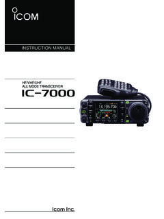
1 INSTRUCTION MANUALHF/50 MHz ALL MODE TRANSCEIVERi756 PRO This device complies with Part 15 of the FCC rules. Operation is sub-ject to the following two conditions: (1) This device may not causeharmful interference, and (2) this device must accept any interferencereceived, including interference that may cause undesired 15:51 Page aiIMPORTANTREAD THIS INSTRUCTION MANUALCAREFULLY before attempting to operate THIS INSTRUCTION contains important safety and operating in-structions for the DEFINITIONSRWARNING HIGH VOLTAGE! NEVERat-tach an antenna or internal antenna connector duringtransmission. This may result in an electrical shock AC to the [ ] jack on thetransceiver rear panel. This could cause a fire or ruinthe more than 16 V DC, such as a 24 Vbattery, to the [ ] jack on the TRANSCEIVER rearpanel. This could cause a fire or ruin the metal, wire or other objects touch anyinternal part or connectors on the rear panel of thetransceiver.
2 This may result in an electric the TRANSCEIVER to rain, snow or or placing the TRANSCEIVER in areas withtemperatures below 10 C (+14 F) or above +50 C(+122 F). Be aware that temperatures on a vehicle sdashboard can exceed 80 C (+176 F), resulting in per-manent damage to the TRANSCEIVER if left there for ex-tended the TRANSCEIVER in excessively dusty en-vironments or in direct the TRANSCEIVER against walls or puttinganything on top of the TRANSCEIVER . This will obstructheat unit in a secure place to avoid inadvertent useby mobile operation, DO NOToperate the trans-ceiver without running the vehicle s engine. Whentransceiver power is ON and your vehicle s engine isOFF, the vehicle s battery will soon become sure the TRANSCEIVER power is OFF before start-ing the vehicle. This will avoid possible damage to thetransceiver by ignition voltage maritime mobile operation, keep the transceiverand microphone as far away as possible from the mag-netic navigation compass to prevent erroneous CAREFUL!
3 The heatsink will become hot when op-erating the TRANSCEIVER continuously for long CAREFUL! If a linear amplifier is connected, setthe TRANSCEIVER s RF output power to less than the lin-ear amplifier s maximum input level, otherwise, the lin-ear amplifier will be Icom microphones only (supplied or optional).Other manufacturer s microphones have different pinassignments, and connection to the IC-756 PROII maydamage the may be received near the following are made in the internal circuit and does not indicate atransceiver MHz, MHz, MHz, MHz (when spectrum scope is ON), MHz, MHzWORDDEFINITIONRRWARNINGP ersonal injury, fire hazard or electricshock may damage may disregarded, inconvenience only. Norisk or personal injury, fire or , Icom Inc. and the are registered trademarks ofIcom Incorporated (Japan) in the United States, the UnitedKingdom, Germany, France, Spain, Russia and/or 15:51 Page bSUPPLIED ACCESSORIESThe TRANSCEIVER comes with the following power cable (OPC-025D).
4 1wHand microphone (HM-36) .. 1eSpare fuses (FGB 30 A) .. 2rSpare fuse (FGB 5 A) .. 1tCW keyer plug (AP-330) .. 111 TABLE OF CONTENTS qwertIMPORTANT .. iEXPLICIT DEFINITIONS .. iPRECAUTIONS .. i1 TABLE OF CONTENTS .. 12 PANEL DESCRIPTION .. 2 13 Front panel .. 2 Microphone (HM-36) .. 9 LCD display .. 10 Screen menu arrangement .. 11 Rear panel .. 123 INSTALLATION ANDCONNECTIONS .. 14 20 Unpacking .. 14 Selecting a location .. 14 Grounding .. 14 Antenna connection .. 14 Required connections .. 15 Advanced connections .. 16 Power supply connections .. 17 Linear amplifier connections .. 18 External antenna tuner connections .. 19 Transverter jack information .. 19 FSK and AFSK (SSTV) connections .. 204 FREQUENCY SETTING .. 21 24 When first applying power (CPU resetting) .. 21 Initial settings .. 21 VFO description .. 22 Frequency setting with the tuning dial .. 23 Direct frequency entry with the keypad .. 23 Advanced tuning functions.
5 245 RECEIVE AND TRANSMIT .. 25 50 Mode selection .. 25 Twin PBT operation .. 25 Notch function .. 26 Noise reduction .. 26 Noise blanker .. 27 DSP filter shape .. 27 RTTY filter/Twin peak filter .. 28 CW reverse mode .. 28 RTTY reverse mode .. 28 CW pitch control .. 29 IF filter selection .. 29 AGC function .. 30 Dualwatch operation .. 31 Split frequency operation .. 32 Quick split function .. 33 RIT and TX .. 34 Monitor function .. 35 VOX function .. 35 Meter function .. 36 SWR reading .. 36 Speech compressor .. 37 Preamp .. 37 Digital voice recorder .. 38 RTTY decoder .. 42 RTTY tuning meter .. 42 Electronic CW keyer .. 43 Memory keyer .. 44 Spectrum scope screen .. 45 Automatic antenna selection .. 46 Dial lock function .. 46 Repeater operation .. 47 Tone squelch operation .. 48 Antenna tuner operation .. 49 Optional external tuner operation .. 506 MEMORY OPERATION .. 51 56 Memory channels .. 51 Memory channel selection.
6 51 Memory channel screen .. 52 Memory channel programming .. 53 Frequency transferring .. 54 Memory names .. 55 Memory clearing .. 55 Memo pads .. 567 SCANS .. 57 61 Scan types .. 57 Preparation .. 57 Programmed scan operation .. 58 F scan operation .. 58 Fine programmed scan/fine F scan .. 59 Memory scan operation .. 59 Select memory scan operation .. 60 Setting select memory channels .. 60 Scan set mode .. 61 Tone scan .. 618 CLOCK AND TIMERS .. 62 63 Setting the current time .. 62 Timer function 62 Setting power-on time .. 63 Setting power-off period .. 63 Timer operation .. 639 SET MODE .. 64 73 Set mode description .. 64 Level set mode .. 65 Display set mode .. 66 DSP filter set mode .. 67 Timer set mode .. 68 Miscellaneous (others) set mode .. 6810 OPTION INSTALLATION .. 74 Opening the TRANSCEIVER s case .. 74 UT-102 VOICE SYNTHESIZER 7411 MAINTENANCE .. 75 77 Troubleshooting .. 75 Fuse replacement.
7 76 Clock backup battery replacement .. 76 Tuning dial brake adjustment .. 77 Frequency calibration (approximate) .. 7712 INTERNAL VIEWS .. 7813 CONTROL COMMAND .. 79 82 Remote jack (CI-V) information .. 7914 SPECIFICATIONS .. 8315 OPTIONS .. 8416 ABOUT CE .. 15:51 Page 1 Front panelqPOWER SWITCH [POWER/TIMER] Push momentarily to turn power ON. Turn the optional DC power supply ON in advance. A/D converter calibration of the DSP unit starts and ittakes approx. 10 sec. Push momentarily to toggle the timer function ONand OFF. (p. 63) The power switch lights while the timer function is ON. Push for 1 sec. to turn power SWITCH [TRANSMIT]Selects transmitting or receiving. The [TX] indicator lights red while transmitting and the[RX] indicator lights green when the squelch is JACK [PHONES]Accepts headphones. Output power: 5 mW with an 8 load. When headphones are connected, the internal speakeror connected external speaker does not KEYER JACK [ELEC-KEY] (p.)
8 43)Accepts a paddle to activate the internal electronickeyer for CW operation. Selection between the internal electronic keyer, bug-keyand straight key operation can be made in keyer setmode. (p. 43) A straight key jack is separately available on the rearpanel. See [KEY] on p. 12. Keyer polarity (dot and dash) can be reversed in keyerset mode. (p. 43) 4-channel memory keyer is available for your conve-nience. (p. 44)tMICROPHONE CONNECTOR [MIC]Accepts the supplied or optional microphone. See p. 84 for appropriate microphones. See p. 9 for microphone connector CONTROL [AF] (inner control)Varies the audio output level from the GAIN CONTROL [MIC GAIN]Adjusts microphone input gain. The transmit audio tone in SSB mode can be adjusted inset mode. (p. 65) How to set the microphone the [MIC] control so that the ALC meter sometimesswings during normal voice transmission in SSB GAINR ecommended level for an Icom microphoneIncreasesDecreasesAFRF/SQLNo audio outputMax.
9 Audio outputDecreasesIncreases(dot)(com)(dash) 22 PANEL DESCRIPTIONTIMERPOWERTRANSMITPHONESELEC- KEYMICTUNER MONITORNBNRAFBALNRRF/SQLMIC GAIN RF POWERCOMP BK-IN DELAY KEY SPEEDF-1F-2F-3F-4F-5HF/50 MHz TRANSCEIVERi756 PRO SSBCW/RTTYAM/FMFILTEREXIT/SETqwert!2!3!4 !5!6yi!1o! 15:51 Page 223 PANEL DESCRIPTIONiRF GAIN CONTROL/SQUELCH CONTROL[RF/SQL] (outer control)Adjusts the RF gain and squelch threshold squelch removes noise output from thespeaker (closed condition) when no signal is re-ceived. The squelch is particularly effective for FM. It is alsoavailable for other modes. 12 to 1 o clock position is recommended for any settingof the [RF/SQL] control. The control can be set as Auto (RF gain control in SSB,CW and RTTY; squelch control in AM and FM) orsquelch control (RF gain is fixed at maximum) in setmode as follows. (p. 69) When setting as RF gain/squelch controlWhile rotating the RF gain control, noise may beheard.
10 This comes from the DSP unit and does notindicate an equipment POWER CONTROL [RF POWER]Continuously varies the RF output power from min-imum (5 W*)to maximum (100 W*).* AM mode: 5 W to 40 W!0 BALANCE CONTROL [BAL] (inner control; p. 31)Adjusts the audio output balance between main andsub readout frequencies while in dualwatch.!1 NOISE REDUCTION LEVEL CONTROL [NR] (outer control; p. 26)Adjusts the noise reduction level when the noise re-duction is in use. Set for maximum readability.!2 NOISE REDUCTION SWITCH [NR](p. 26)Switches the noise reduction ON and OFF.!3 NOISE BLANKER SWITCH [NB](p. 27) Switches the noise blanker ON and OFF whenpushed. The noise blanker reduces pulse-typenoise such as that generated by automobile igni-tion systems. This function cannot be used forFM, or non-pulse-type noise. Enters the noise blanker level set mode whenpushed for 1 sec.!4S/RF METER(p. 36)Shows the signal strength while receiving. Showsthe relative output power, SWR, ALC or compres-sion levels while transmitting.