Transcription of ALLOWABLE STRESS DESIGN TEK 14-7B OF …
1 An information series from the national authority on concrete masonry technology ALLOWABLE STRESS DESIGN TEK 14-7B . OF concrete masonry Structural (2009). INTRODUCTION compatibility of strains. Plane sections before bending remain plane after bend- concrete masonry elements can be designed by using ing. Therefore, masonry strain is directly proportional one of several methods in accordance with Building Code to the distance from the neutral axis. Requirements for masonry Structures (ref. 1): empirical STRESS is linearly proportional to strain within the al- DESIGN , strength DESIGN , or ALLOWABLE STRESS DESIGN . This lowable STRESS range. TEK provides a basic overview of DESIGN criteria and For reinforced masonry DESIGN , all tensile stresses are requirements for concrete masonry assemblies designed resisted by the steel reinforcement. The contribution using the ALLOWABLE STRESS DESIGN provisions contained in of the masonry to the tensile strength of the element Chapter 2 of the Building Code Requirements for Ma- is ignored.
2 Sonry Structures. For masonry DESIGN in accordance with The units, mortar, grout, and reinforcement, if present, the empirical or strength DESIGN provisions, the reader act compositely to resist applied loads. is referred to TEK 14-8B Empirical DESIGN of concrete Based on this assumed DESIGN model, the internal masonry Walls (ref. 4) and TEK 14-4B Strength DESIGN distribution of stresses and resulting equilibrium is il- Provisions for concrete masonry (ref. 5), respectively. lustrated in Figure 1 for unreinforced masonry and Figure The content presented is based upon the require- 3 for reinforced masonry . ments of the 2006 International Building Code (ref. 2a). and 2009 International Building Code (ref. 2b), which in DESIGN LOADS. turn reference the 2005 and 2008 editions of the Building Code Requirements for masonry Structures (ref. 1a and Utilizing ALLOWABLE STRESS DESIGN , masonry elements 1b), respectively.
3 Where DESIGN assumptions or model- are sized and proportioned such that the anticipated service ing conditions differ between cited references, they are level loads can be safely and economically resisted using identified accordingly here. Otherwise, the ALLOWABLE the specified material strengths. The specified strength of STRESS DESIGN provisions between the 2005 and 2008 masonry and reinforcement are in turn reduced by appro- Building Code Requirements for masonry Structures priate safety factors. Minimum DESIGN loads for ALLOWABLE are the same. This TEK is intended only to provide a STRESS DESIGN are included in Minimum DESIGN Loads for general review of the pertinent ALLOWABLE STRESS DESIGN Buildings and Other Structures (ref. 3) or obtained from criteria. Tables, charts, DESIGN examples and additional the International Building Code (IBC) (ref. 2). For load aids specific to the ALLOWABLE STRESS DESIGN of concrete combinations that include wind or earthquake loads, the masonry elements can be found in the TEK listed in the code-prescribed ALLOWABLE stresses are permitted to be related TEK box, below.
4 Increased by one-third when using the alternative basic ALLOWABLE STRESS DESIGN is based on the following load combinations of the IBC. DESIGN principles and assumptions: Using ALLOWABLE STRESS DESIGN , the calculated DESIGN Within the range of ALLOWABLE stresses, masonry ele- stresses on a masonry member (indicated by lowercase ments satisfy applicable conditions of equilibrium and f) are compared to code-prescribed maximum ALLOWABLE Related TEK: Keywords: ALLOWABLE loads, ALLOWABLE STRESS , ALLOWABLE STRESS DESIGN , 14-3A, 14-5A, 14-15B, axial strength, building code provisions, flexural strength, reinforced 14-19A, 14-20A, 14-22 concrete masonry , shear strength, structural DESIGN , unreinforced con- crete masonry NCMA TEK (replaces TEK) 1. stresses (indicated by a capital F). The DESIGN is accept- given by Equation 1 is negative, the masonry section is able when the calculated applied stresses are less than or in compression and the compressive STRESS limitation of equal to the ALLOWABLE stresses (f < F).
5 Equation 2 must be met. 1. UNREINFORCED masonry fb Fb =f m Eqn. 2. 3. For unreinforced masonry , the masonry assembly (units, mortar, and grout if used) is designed to carry Unreinforced Axial Compression and all applied stresses (see Figure 1). The additional ca- Flexure pacity from the inclusion of reinforcing steel, such as While unreinforced masonry can resist flexural ten- reinforcement added for the control of shrinkage crack- sion stresses due to applied loads, unreinforced masonry ing or prescriptively required by the code, is neglected. may not be subjected to net axial tension, such as that due Because the masonry is intended to resist both tension to wind uplift on a roof connected to a masonry wall or and compression stresses resulting from applied loads, the overturning effects of lateral loads. While compres- the masonry must be designed to remain uncracked. Table 1 ALLOWABLE Flexural Tensile Unreinforced Out-of-Plane Flexure Stresses, psi (kPa).
6 ALLOWABLE flexural tension values as prescribed in Building Code Requirements for masonry Struc- Mortar types: tures, vary with the direction of span, mortar type, Direction masonry cement bond pattern, and percentage of grouting as shown of flexural Portland cement/ or air-entrained in Table 1. For assemblies spanning horizontally tensile lime or portland cement/. between supports, the code conservatively assumes STRESS and mortar cement lime that masonry constructed in stack bond cannot reli- masonry type M or S N M or S N. ably transfer flexural tension stresses across the head joints. As such, the ALLOWABLE flexural tension values Normal to bed joints: parallel to the bed joints (perpendicular to the head Solid units 40 (276) 30 (207) 24 (166) 15 (103). joints) for stack bond construction are assumed to be Hollow units A. zero for DESIGN purposes unless a continuous section Ungrouted 25 (172) 19 (131) 15 (103) 9 (62).
7 Of grout crosses the head joint, such as would occur Fully grouted 65 (448) 63 (434) 61 (420) 58 (400). with the use of open-ended units or bond beam units with recessed webs. Parallel to bed joints in running bond: Because the compressive strength of masonry is Solid units 80 (552) 60 (414) 48 (331) 30 (207). much larger than its corresponding tensile strength, Hollow units the capacity of unreinforced masonry subjected to Ungrouted &. net flexural stresses is almost always controlled by partially grouted 50 (345) 38 (262) 30 (207) 19 (131). the flexural tension values of Table 1. For masonry Fully grouted 80 (552) 60 (414) 48 (331) 30 (207). elements subjected to a bending moment, M, and a compressive axial force, P, the resulting flexural Parallel to bed joints in stack bond: bending STRESS is determined using Equation 1. Continuous grout section parallel to bed jointsB 100 (690) 100 (690) 100 (690) 100 (690).
8 Mt P Other 0 (0) 0 (0) 0 (0) 0 (0). fb = . 2I n An Eqn. 1. A. For partially grouted masonry , ALLOWABLE stresses shall be determined on the basis of linear interpolation between fully TEK 14-1B, Section Properties of concrete Ma- grouted hollow units and ungrouted hollow units based on sonry Walls (ref. 6) provides typical values for the amount (percentage) of grouting. net moment of inertia, In, and cross-sectional area, An, B. The 2005 edition of Building Code Requirements for Ma- for various wall sections. If the value of the bending sonry Structures (ref. 1a) does not directly provide for ALLOWABLE STRESS , fb, given by Equation 1 is positive, the masonry flexural tension stresses parallel to bed joints with continuous section is controlled by tension and the limiting val- grout sections. These DESIGN stresses have been clarified in the ues of Table 1 must be satisfied. Conversely, if fb as 2008 edition (ref.)
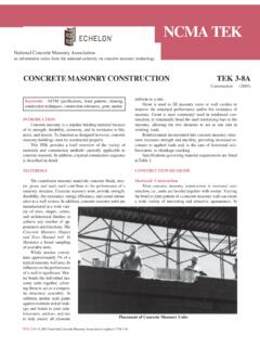
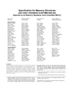
9 1b). 2 NCMA TEK. able stresses to the applied loads per Equation 6. This fb check ensures that the critical sections remain uncracked under DESIGN loads. f a fb + 1. Fa Fb Eqn. 6. Unreinforced Shear Shear stresses on unreinforced masonry elements are calculated using the net cross-sectional properties of the masonry in the direction of the applied shear force using the following relation: VQ. fv =. I nb Eqn. 7. Equation 7 is applicable to determining both in-plane Wall width and out-of-plane shear stresses. Because unreinforced masonry is designed to remain uncracked, it is not neces- Figure 1 Unreinforced masonry STRESS sary to perform a cracked section analysis to determine Distribution the net cross-sectional area of the masonry . The theoretical distribution of shear STRESS , fv, along sive stresses from dead loads can be used to offset tensile the length of the shear wall (Figure 2) for in-plane loads, stresses, reinforcement must be incorporated to resist the or perpendicular to any wall for out-of-plane loads, is resulting tensile forces when the element is subject to a parabolic in shape for a rectangular cross-section.
10 The net axial tension. calculated shear STRESS due to applied loads, fv, as given When masonry elements are subjected to compres- by Equation 7 cannot exceed any of the code-prescribed sive axial loads only, the calculated compressive STRESS ALLOWABLE shear stresses, Fv, as follows: due to applied load, fa, must not exceed the ALLOWABLE a) f m psi ( f m MPa). compressive STRESS , Fa, as given by Equations 3 or 4, as b) 120 psi (827 kPa). appropriate. c) For running bond masonry not grouted solid: For elements having h/r < 99: 37 psi + An (255 + /An kPa). 1 h . 2. d) For stack bond masonry with open end units and fa F. = a f m 1 P. 4 140r . Eqn. 3 M. For elements having h/r > 99: P V Compressive 2 STRESS , fb 1 70r . f a Fa =f m M. 4 h Eqn. 4 Compressive A further check for stability against an eccentrically STRESS , fb applied axial load is included with Equation 5, whereby the axial compressive load, P, is limited to one-fourth the buckling load, Pe.