Transcription of Altivar 18 Telemecanique
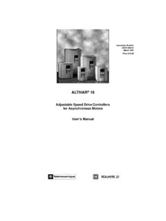
1 Guide d'exploitationUser's manualBedienungsanleitungGu a de explotaci n Merlin GerinTelemecaniqueSquare DModiconAltivar 18 Telemecaniquevariateurs de vitesse pourmoteurs asynchrones,variable speed controllersfor asynchronous motors,Frequenzumrichterf r Drehstrom-Asynchronmotoren,variadores de velocidadpara motores as AISA ltivar 18 Variateur de vitesse pour moteurs asynchronesPage 2 Speed controller for asynchronous motorsPage 34 Umrichter f r Drehstrom-AsynchronmotorenSeite 66 Variador de velocidad para motores as ncronosP gina 98 ENGLISHDEUTSCHESPA OL34 ENGLISHNOTEWARNINGWhen the speed controller has power on, a number of components are connected to the is extremely dangerous to touch switching off the supply to the Altivar wait for 1 minute before touching the equipment.
2 Thisis the time taken for the capacitors to operation the motor can be stopped or started by inhibiting the start command with thespeed controller still connected to the supply. For personnel safety during maintenanceelectronic locking should not be used, the supply should be speed controller incorporates safety devices which can shutdown the speed controller andstop the motor in the event of a fault. These faults may be caused by a mechanical blockage ofthe motor or alternatively problems with the electrical removal of the problem may cause the motor to re-start, creating danger for certain machinesand installations, especially those which must conform to safety such cases, therefore, the user must take precautions to avoid re-starting of the motor.
3 Adevice such as a speed detector should be incorporated to remove the supply in the event of anunscheduled stopping of the equipment has been designed to conform to IEC general, power to the speed controller must be switched off before any electrical or mechanicalintervention on the installation or products and materials presented in this document may be changed or modified at any time,either from a technical point of view or in the way they are operated. Their description can in noway be considered speed controller must be installed and set up in accordance with international and nationalstandards. This compliance is the responsibility of the systems integrator who must respect theEuropean community EMC directive amongst specifications contained in this document must be applied in order to comply with theessential requirements of the EMC Altivar 18 must be considered a component.
4 It is neither a machine nor a piece of equipmentready for use in accordance with European directives (machinery directive and electromagneticcompatibility directive). It is the responsibility of the user to ensure that his machine meets " Altivar 18"34 Preliminary checks38 Choice of speed controller38 Available torque39 Technical characteristics40 Dimensions - Mounting recommendations41 Mounting in a wall-fixing or floor standing enclosure42 Electromagnetic compatibility43 Accessing terminals - Power terminals44 and 45 Control terminals46 Connection diagram47 Functions which do not require adjustment48 Logic and analog input functions which can be configured49 to 51 Function compatibility table52 Installation53 to 62 Maintenance - Replacement and repairs63 Maintenance
5 Assistance6438 ENGLISHP reliminary checksRemove the Altivar 18 from its packaging, and check that it has not been damaged in transit. Check that thereference of the speed controller on the label is the same as that on the delivery note and corresponds to theorder of speed supplyMotorAltivar 18 PowerLinePowerPermanent Maximum PowerReferenceWeightsupplycurrent (1)indicatedoutputtransientdissipatedvol tageat U1at U2on platecurrentcurrent (2) at Hzsingle phase (1) Typical value without additional inductance.(2) For 60 Altivar 18 is designed to supply the required power for the appropriate torqueContinuous operationFor self-ventilated motors, motor cooling is linked to speed.
6 Derating occurs at speeds of less than half thenominal in overspeedSince the voltage can no longer change with the frequency, there is a decrease in motor induction resultingin a loss of torque. Consult the manufacturer to find out whether the machine can operate in characteristics :1 Continuous usable torque : self-ventilated motor2 Continuous usable torque : force-ventilatedmotor3 Transient overtorque : typical curve at 10 %Value : Tn for 60 sNote : With a special motor, the nominal frequency and the maximum frequency can be adjusted from 40 to320 (Hz)0,525305060132110,951,5T/Tn1,240 ENGLISHT echnical characteristicsEnvironmentDegree of protectionIP31IP20 without the blanking cover on the topVibration and shock gn from 10 to 50 Hzin accordance with EN501782 gn from 50 to 150 HzDegree of pollutionDegree 2 according to IEC664.
7 Protect the speed controller fromdust, corrosive gases, splashing liquid, maximum humidity93 % without condensation or dripping water. If there is a risk ofcondensation, provide a heating systemAmbient air temperatureFor storage : - 25 C to + 65 Cin accordance with EN50178 For operation :-10 C to + 40 C without derating, with the blanking cover-10 C to + 50 C without derating, without the blanking coverMaximum operating altitude1000 m without derating. Above this, derate the current by 3 %for each additional 1000 mElectrical characteristicsPower supplyVoltage- single phase : 200 V - 15 % to 240 V + 10 %- 3-phase : 200 V - 15 % to 230 V + 10 % 380 V - 15 % to 460 V + 10 %Frequency50/60 Hz 5%Output voltageMaximum voltage equal to mains voltageOutput frequency to 320 HzMaximum transient current150 % of speed controller nominal current for 60 secondsBraking torque30 % of the nominal motor torque without brake resistor (typicalvalue).
8 Up to 150 % with brake resistor as an optionFrequency resolution- Display : Hz- Analog inputs : Hz for 100 Hz maximumSwitching frequencyCan be adjusted from to 12 kHzSpeed controller protection and- Electrical isolation between power and control circuits (inputs,safetyoutputs, supplies)- Protection against short-circuits :. internal supplies available. between output phases U - V - W. between the output phases and earth for ratings to 15 kW- Thermal protection from excessive overheating and overcurrents- Under and overvoltage supply- Overvoltage safe on brakingMotor protectionProtection integrated in the speed controller by calculating I2t41 ENGLISHD imensions - Mounting recommendationsDimensionsATV18iiiiATV18a bcGH U09M2, U18M21121821211001705U29M2, U18N4, U29N41491841571371725U41M2, U54M2, U72M2, U41N4, U54N4, U72N41852151581712026U90M2, D12M2, U90N4, D12N42103001701902807D16N4.
9 D23N424539019022537010 Mounting recommendationsMount the unit placing close to any heating enough free space to ensure that sufficient air can circulate for cooling. The unit is ventilated from thebottom : remove the blanking cover from the top (self-adhesive film).Ventilation flow rateATV-18U09M2, U18M2, U18N4 : not , U29N4 : m3 , U54M2, U72M2, U41N4, U54N4, U72N4 m3 , D12M2, U90N4, D12N4, D16N4, D23N4 m3 ==H== 50 50 100 10042 ENGLISHM ounting in a wall-fixing or floor-standing enclosureObserve the mounting recommendations given on page ensure air circulation in the speed controller :- provide ventilation louvres,- ensure that ventilation is sufficient.
10 If not install forcedventilation with a filter,- use special filters in IP 54,- remove the blanking cover from the top of the and damp proof metal enclosure (degree of protection IP 54)The speed controller needs to be mounted in a dust and damp proof enclosure under certain environmentalconditions : dust, corrosive gas, high humidity with a risk of condensation or dripping water, splashing liquid, avoid hot spots in the speed controller, if it is a non-ventilated model, add a fan to circulate the air insidethe means that the speed controller can be used in an enclosure where the maximum internal temperaturecan reach 50 the size of the enclosureMaximum thermal resistance Rth ( C/W) : = maximum temperature in the enclosure in C,Rth = - e e = maximum external temperature in C,PP= total power dissipated in the enclosure in dissipated by the speed controller.