Transcription of Amphenol
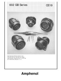
1 Amphenol 162GB Series Miniature Bayonet Lock connectors Amphenol CONTENTS Pages Introduction to 162GB crimp connectors 2 Audio Applications 2 Cable Assembly Facilities at Amphenol Ltd 2 MIL-C-26482 Qualification Approval Tests 3-4 DEF 5325 Qualification Approval Tests Table of Shell Styles 5 Insert Availability and Voltage Ratings 6-7 How to Order 162GB crimp connectors 8 Box Mounting Receptacles 9-10 Single Hole Fixing Receptacles 11-12 Cable Mounting Receptacles 13-14 Plugs 15-16 Plugs with optional Coupling Rings 17-18 Cable Accessories 19 Cables to DEF 10 20 Accessories Dust Caps 21-28 AIA Backshells Interconnection Accessories 29-31 Interconnection Accessories Installation Procedure 32-33 Interconnection Accessories Shield Term Process 34 Key/keyway Orientations 35 Insert Orientations 36 162GB crimp Assembly Instructions
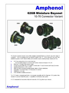
2 37-42 2 Development and manufacture of 162GB miniature bayonet lock connectors has been closely coordinated with the solder version. The entire programme has been carried out at Amphenol s Whitstable Plant. The precision machinery and measurement control processes used for the production of 162GB crimp connectors are the same as those used to produce 62GB solder connectors . Full intermountability and intermateability are absolutely guaranteed.
3 162GB Series crimp connectors share many of the features of 62GB solder connectors . Coupling is achieved with a triple-track bayonet locking system which gives positive alignment on all shell sizes. When connector halves are fully mated there is a definite click. Inspection holes in the coupling ring will then reveal the bayonet pins on the receptacle which are clearly marked in yellow. The Amphenol design means simplified removal of coupling rings for servicing or replacement as they are front demountable.
4 In addition there is a rough grip heavy duty style for arduous conditions and a lever coupling ring which allows extremely close mounting of connectors . The method of sealing is the same as for 62GB connectors ; using peripheral seals on the rubber inserts and sealing the mating shells with a square section gasket. Wire sealing is by multiple risers in the rear grommet. Derating connectors must be derated under the following operating temperatures: 1.
5 At elevated temperatures, the current ratings are reduced as show in the table on page 10. 2. At high altitudes, revised voltage ratings become effective as shown on page 11. 3. When connectors to different specifications are intermated ( BS 9522-N001 and MIL-C-26482), the combination must not be operated under conditions more severe than the less stringent clause of either specification. Amphenol 162GB connectors are designed to meet the most stringent requirements of both specifications.
6 Audio Applications Contacts are suitable for tinsel cord applications. Cable Assemblies Amphenol is fully equipped to undertake the preparation of all types of cable assemblies complying with the military vehicles and engineering establishments and fighting vehicles requirements of the Ministry of Defence the Ministry of Environment (Motorways) for motorway control equipment the Post Office manufacturing code and to the British Standards Institute when applicable to Cable systems.
7 Control procedures carried out in accordance with MIN DEF 05-21. Approval numbers BS 9000, 1043/M and CAA AD/1450/58. Moulded terminations form a specialised service by the company. The process offers such advantages as a waterproof seal between cable and connector back-end, mechanical protection, and a homogeneous joint between moulding and cable. Other Amphenol Products Amphenol products include: printed circuit, rack and panel, microminiature, audio; hermetic and connectors ; integrated circuit components; trimming and precision potentiometers; concentric and digital microdials; cable, cable assemblies; fans and blowers; relays and keys; chokes and coils; coaxial switches.
8 Amphenol 162 GBCrimp ConnectorsDESIGNED TO COMPLY WITH MIL-C-26482 AND BS 9522-N0001, THE SUCCESSOR TODEF 5326 Patt. 603 3 Tests Brief Description Examination of Product Maintenance Ageing crimp only There is no damage to the contacts or connectors after 10 removals and insertions of the contacts Contact Insertion and Removal Forces crimp only Insertion does not exceed N (15lbf.) For individual contacts. Removal does not exceed (10lbf.) crimp Contact Contact locking mechanisms withstands the following minimum axial forces: CONTACT SIZE 20 16 12 FORCE (N) 89 111 133 FORCE (LBF) 20 25 30 Contact Retention Axial displacement does not exceed ( ) when pressure is applied from face side.
9 Operating Forces Torque measurement of mating and unmating. Ranges from Nm. (8 lbf. in.) on shell size 8 to Nm. (44 lbf. in.) on shell size 24 couplings. Insulation Resistance, Room Temperature Unmated connectors tested in accordance with Method 302 test condition B of MIL-STD-202. Dielectric Withstanding Voltage (Sea Level) Mated and unmated connectors tested in accordance with Method 301 of MIL-STD-202. Dielectric Withstanding Voltage (Altitude) Tested in accordance with Method 105, test condition C of MIL-STD-202.
10 After 30 minutes tested in accordance with Method 301 of MIL-STD-202 unmated and mated. Initial Contact Resistance Between 45 and 95 millivolts drop on wire sizes from 24 to 12. crimp contacts to meet MIL-C-23216. Thermal Shock Unmated connectors tested in accordance with Method 107, condition B of MIL-STD-202 except min. temp is 55oC. Insulation Resistance at Elevated Temps (Short Time) (Long Time) Greater than 3 megohms 250 hr at 125oC Greater than 12 megohms 1000 hr at 105oC Durability 500 cycles of coupling and uncoupling Vibration In accordance with Method 204 Condition B of MIL-STD 202 Shock Impulses of 50 G s duration of 11 1 milliseconds Moisture Resistance In accordance with Method 106 of MIL-STD-202 Corrosion Salt Spray to Method 101 Condition B of MIL-STD-202 Operating Forces From Nm.