Transcription of Analog & Digital Electronics
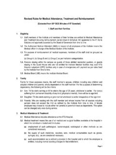
1 Analog & Digital ElectronicsCourse No: PH-218 Lec-13: Multistage AmplifiersCourse Instructors: Dr. A. P. VAJPEYID epartment of Physics, Indian Institute of Technology Guwahati, India1 CharacteristicCommon BaseCommon EmitterCommon CollectorInput impedanceLowMediumHighOutput impedanceVery HighHighLowPhase Angle0o180o0oVoltage GainHighMediumLowCurrent GainLowMediumHighPower GainLowVery HighMediumMultistage Amplifier:2 Power GainLowVery HighMedium Common emitter amplifier is most popular BJT amplifier due to high power gain. Ideal amplifier should have high input impedance , low output impedance , high voltage and current gain.
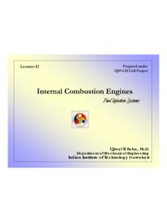
2 Single Stage amplifier is not able to provide enough gain, power and full-fill all the requirement of an ideal amplifier ---------Need Multistage amplifierMultistage Amplifier: Characteristics33 Practical amplifiers usually consist of a number of stages connected in Amplifiers The first (input) stage is usually required to provide a high input resistance a high common-mode rejection for a differential amplifier Middle stages are to provide majority of voltage gain4 majority of voltage gain conversion of the signal from differential mode to single-end mode shifting of the dc level of the signal The last (output) stage is to provide a low output resistance in order to avoid loss of gain and provide the current required by the load (power amplifiers)Multistage Amplifier.
3 Gain Calculation1 2 3vTvvvAA A A=K1 2 3iTiiiAA A A=KpTvTiTAA A=Procedure:1. Do dc analysis2. Find r efor each rCfor each stage55pTvTiTAA A= rCfor each stage4. Using r eand rCto find Avfor each stageInput impedance of next stage is the load of current stage.(Zinof next stage is RLof current stage)incoVjXRRV)( =)/1(CjRRVVA inoutv ==1A=Multistage Amplifiers: Frequency Response6)2/1(1fCRjAv =RCfffjAv 2/1)/(1111= =)/(tan)/(111121ffffAv +=If n identical stages are connected together then overall voltage gain at lower frequency is given by:Av-low = Av1-low Av2-low Avn-low = (Av-low)nwhere nis the number of cascaded stages.
4 Since Av1-low= Avn-lowMultistage Amplifiers: Low cut off Frequency 7 For lower cutoff frequency : Av-low / Av-mid)overall= 1/ 2()nnmidvlowvoverallmidvlowvffjAAAA/(111 = = 21])/(1[121=+ nlowcff1211 = nlowcffMultistage Amplifiers: High Cutoff Frequency inccoVjXRjXV)( =)(11 CRjVVAinoutv +==)/(11)2(112ffjfCRjAv+=+= )/(tan)/(112122ffffAv +=RCf 2/12=where8()nnmidvhighvoverallmidvhighv ffjAAAA2/(11+= = For cutoff frequency : Av-high / Av-mid)overall= 1/ 221])/(1[122=+ nhighcff1212 = nhighcffThe cutoff frequencies for cascaded amplifiers with identical values of fc1 and fc2are found usingwhere nis the number of cascaded stages.
5 1211 = nclowcff1212 = nchighcfflowchighcoverallffBW =Multistage Amplifiers: Frequency ResponseWhen Each stage has a different lower & upper critical frequency9 When Each stage has a different lower & upper critical frequency When the lower critical frequency, fcL, of each amplifier stage isdifferent, the dominant lower critical frequency, f'cLequals thecritical frequency of the stage with the highest fcL. When the upper critical frequency fcu, of each amplifier stage isdifferent, the dominant upper critical frequency f'cu, equals thecritical frequency of the stage with the lowest fcuIn a multistage amplifier the output of one stage makes the input of the next stage.
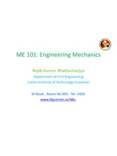
6 Normally a network is used between two stages so that a minimum loss of voltage occurs when the signal passes through this network to the next stage. Also the dc voltage at the output of one stage should not be permitted to go to the input of the next. Otherwise, the biasing of the next stage are disturbed. The three couplings generally used are. couplingTypes of Coupling: coupling2. Transformer coupling3. direct couplingProblem: A transformer coupling is used in the final stage of a multistage amplifier. If the output impedance of transistor is 1kohm and the speaker has a resistance of 10ohm.
7 Find the turn ratio of the transformer in order to transfer maximum power to the load (speaker). Solution: For maximum power transfer, the impedance of the primary should be equal to the output impedance of the transistor and impedance of secondary should be equal to the load impedance . Primary impedance = output impedance of transistor = 1kohm; Secondary impedance = impedance of load = 10ohm2 =pSpSNNRRNs/ Np=1:10RC coupling 11It has excellent frequency response in a audio frequency range and cheaper in drawback of this approach is the lower frequency limit imposed by the coupling capacitor and poor impedance matching.
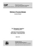
8 CScapacitor is used to make other point of transformer grounded, so that ac signal is applied between base and ground. The drawback of this approach is the poor frequency couplingTransformer coupling is mainly used in power amplifiers. 2 =pSpSNNRR12 Direct couplingDirect coupling is the couplingmethod in which the output of onestage is directly connected to theinput of the next the frequency response curve look like for direct coupling?CharacteristicR-C couplingTransformercouplingDirect CouplingFrequencyResponseExcellent in audio frequency rangePoorBestCostLessMoreLeastSpace & WeightLessMoreLeastComparison of different type of coupling13 WeightImpedance MatchingNot goodExcellentGoodUseVoltage amplificationPower amplification amplifying extremely low frequencyCascode amplifierWhile the C-B amplifier is known for wider bandwidth than the C-E configuration, the low input impedance (10s of ) of C-B is a limitation for many applications.
9 The solution is to precede the C-B stage by a low gain C-E stage which has moderately high input impedance (k s).The cascode amplifier is combination of common-emitter and common-base key to understanding the wide bandwidth of the cascode configuration is the Miller common-base configuration is not subject to the Miller effect because the grounded base shields the collector signal from being fed back to the emitter input. Thus, a C-B amplifier has better high frequency way to reduce the common-emitter gain is to reduce the load resistance. The gain of a C-E amplifier is approximately RC/re. The collector load RCis the resistance of the emitter of the C-B stage loading the C-E stage.
10 CE gain amplifier gain is approximately Av= RC/re=1. This Miller capacitance is Cmiller= Ccbo(1-Av) = Ccbo (1-(-1)=2 Ccbo. Cascode amplifier15 Ccbo (1-(-1)=2 Ccbo. We now have a moderately high input impedance C-E stage without suffering the Miller effect, but no C-E stage voltage gain. The C-B stage provides a high voltage gain. The total current gain of cascode is as current gain of the C-E stage is 1 for the C-B is . A cascode amplifier has a high gain, moderately high input impedance , a high output impedance , and a high bandwidth. Darlington AmplifierIt consists of two emitter followers in cascaded mode.))