Transcription of ANALYSIS OF HAMMING WINDOW USING …
1 International Journal of Scientific Research Engineering &Technology (IJSRET) Volume 1 Issue4 pp 015-020 July 2012 www. ISSN 2278 - 0882 IJSRET @ 2012 ANALYSIS OF HAMMING WINDOW USING ADVANCE PEAK WINDOWING METHOD Akhilesh Chandra Bhatnagar1, R. L. Sharma2, Rajesh Kumar3 Ajay Kumar Garg Engineering College, Ghaziabad, India ABSTRACT Many WINDOW functions are widely used in digital signal processing for various applications in signal ANALYSIS and estimation, digital filter design and speech processing. In literature many windows have been proposed like ultra spherical WINDOW , Kaiser WINDOW and HAMMING WINDOW with different specifications. But since they are suboptimal solutions, as there is a tradeoff between various factors and the best WINDOW depends upon the related application.
2 The paper is based upon the performance of various windows. The Kaiser WINDOW has been used to design a better FIR Filter in terms of ripple ratio, side-lobe roll off ratio and main-lobe width with its advantages of no power series expansion in frequency domain hence need less hardware. The spectral characteristic of HAMMING WINDOW is compared with other windows like Kaiser WINDOW . A modification is also introduced in HAMMING WINDOW to perform better in terms of ripple ratio as compared to Kaiser USING advanced Peak windowing method. Index Terms FIR filter design, HAMMING WINDOW , Kaiser WINDOW , Main-lobe width, Side-lobe roll-off ratio, Ultra spherical WINDOW , WINDOW function. I. INTRODUCTION Many WINDOW functions are widely used in digital signal processing for various applications in signal ANALYSIS and estimation, digital filter design and speech processing [1].
3 In literature many windows have been proposed like ultra spherical WINDOW , Kaiser WINDOW and HAMMING WINDOW with different specifications. But since they are suboptimal solutions, as there is a tradeoff between various factors and the best WINDOW depends upon the related application. Kaiser WINDOW (also called I0-sinh WINDOW ) [3] is a well known flexible WINDOW and widely used for the spectrum ANALYSIS and FIR filter design applications since it achieves a close approximation with the discrete prolate spheroidal functions that have the maximum energy concentration in the main-lobe. Because of the difficulty of computing the prolate function, a much simpler approximation USING the zeroth-order modified Bessel function of the first kind was used which resulted in Kaiser WINDOW , defined as power amplifier at the transmitter end.
4 Clipping degrades the bit-error-rate (BER) performance and causes spectral spreading. One way to solve this problem is to force the amplifier to work in its linear region. Unfortunately, such a solution is not power efficient. Power efficiency is necessary in wireless communication as it provides adequate area coverage, saves power consumption, and allows small-size terminals. It is, therefore, important to aim at a power efficient. FFT based measurements are subject to errors from an effect known as leakage. This effect occurs when the FFT is computed from of a block of data which is not periodic. To correct this problem appropriate windowing functions must be applied. The user must choose the appropriate WINDOW function for the specific application.
5 When windowing is not applied correctly, then errors may be introduced in the FFT amplitude, frequency or overall shape of the spectrum. This application note describes the phenomenon of leakage, the various windowing functions and their strengths and weaknesses, and examples are given for various applications. In this paper, we propose an advanced peak windowing method. The proposed method overcomes the drawback of the conventional one while maintaining almost the same spectral mask and providing more efficient BER performance. Through a numerical ANALYSIS and computer simulation, we show that the proposed scheme can be implemented by USING a matrix form and exceeds the conventional windowing method. International Journal of Scientific Research Engineering &Technology (IJSRET) Volume 1 Issue4 pp 015-020 July 2012 www.
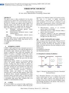
6 ISSN 2278 - 0882 IJSRET @ 2012 II. SYSTEM MODEL Fig. 1 shows an OFDM block diagram under consideration. The binary information bits are mapped to complex-valued MQAM symbols in a 2-dimensional signal constellation. The output of the mapper is serial-to-parallel converted and processed USING an N -point complex inverse fast Fourier transform (IFFT). The N complex-valued time domain signals are then followed by a guard interval (GI), which contains the number of last L 1 samples (N > L). The GI consists of a partial repetition of an OFDM symbol so it does not affect the PAPR. Therefore, we do not take the GI into consideration here. Passing through a PAPR reduction block such as peak windowing, the signals undergoes a digital-to analog conversion and are transmitted after high power amplifier.
7 At the receiver, the received signals can be demodulated by the reverse process of the transmitter. Fig1: OFDM transmitter with peak windowing If we assume the input complex-valued data symbol of N subcarriers as Xk for k = 0, L, N 1, the output signal of the IFFT block is given by 120(), 0,kNjf tKKxtX etNT where fk is the frequency of the k -th subcarrier defined as f = k f (f = 1/NT) and T is the sample interval. III. ADVANCED PEAK WINDOWING METHOD In this section, we outline the conventional peak windowing method and propose a new PAPR reduction technique. The proposed method overcomes the drawback of the conventional method when successive peaks emerge within a half of the WINDOW size. The clipping method is the simplest way to reduce PAPR. However, it distorts signals nonlinearly and significantly increases the out-of-band radiation.
8 A different approach is to multiply large signal peaks with a certain WINDOW function. In order to maintain the out-of-band radiation within a certain level, it is benefit to increase the WINDOW length. On the other hand, the WINDOW should not be too long, because a long widow length implies that many signal samples are affected, which degrades the BER performance. Examples of suitable WINDOW functions are the Cosine, Kaiser, HAMMING , and Hanning WINDOW [11]. In general, Kaiser WINDOW is used because it is easy to shape spectrum by changing WINDOW length and shape parameter [12]. The Kaiser WINDOW function with WINDOW length M +1 and shape parameter is given by ( ) cos2, 0wnnnNN (1) Where the WINDOW length is 1LN , is defined as = M/2, I0(.)
9 Represents the zeroth order modified Bessel function of the first kind, and M is a positive even number. The peak windowing can be expressed as a multiplication of input signals with a scale function at the peak point [7]. It can be accomplished by ( )( ) ( )x ns n x n , (2) Where, s (n) means the scale function that is used to reduce the peak signal level. In addition, the scale function can be expressed as a convolution between weighting coefficient c(n) and WINDOW function w(n) : ( ) 1( ) ()ksnc k w n k (3) International Journal of Scientific Research Engineering &Technology (IJSRET) Volume 1 Issue4 pp 015-020 July 2012 www.
10 ISSN 2278 - 0882 IJSRET @ 2012 In order to apply the scale function at the highest value among the oversampled signals exceeding the given threshold level, the peak sample index ni and its value x( ni) should be defined as ( )max( ) ,ijinn nx nx n (4) where ni is the non-uniformly spaced sample index running over the specific set of samples, which exceed the threshold A . Also, ni- represents a sample index on the rising edge of the signal, where it first exceeds the threshold A, while ni+ represents a sample index, where the signal peak dips below the threshold A. The weighting coefficient c (ni) can be chosen in a way that the resulting envelope xs(n does no longer cross the desired threshold level A at the peak point: ( ) 1/ ( )iic nA x n (5) Such a peak windowing method can limit the peak value to the threshold level while maintaining its spectrum.)