Transcription of Analysis of Statically Determinate Structures
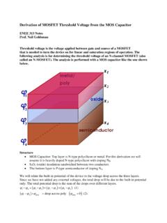
1 1!Idealized Structure!Principle of Superposition!Equations of Equilibrium!Determinacy and Stability!Beams!Frames!Gable Frames!Application of the Equations of Equilibrium! Analysis of Simple Diaphragm and ShearWall Systems ProblemsAnalysis of Statically Determinate Structures2 Classification of Structures Support Connectionstypical roller-supported connection (concrete)typical fixed-supported connection (concrete)typical pin-supported connection (metal)stiffenersweldweldtypical fixed-supported connection (metal)3fixed-connected jointpin-connected jointfixed supportABPactual beamL/2L/2torsional spring jointpin supporttorsional spring supportidealized beamABL/2L/2P4 One unknown. The reaction is aforce that acts perpendicular to the surface at the point of unknown. The reaction is aforce that acts perpendicular to the surface at the point of unknown. The reaction is aforce that acts in the direction of the cable or unknown. The reaction is aforce that acts perpendicular to the surface at the point of of ConnectionIdealized SymbolNumber of UnknownsReactionTable 2-1 Supports for Coplanar Structures (3)F(4)F(1) Light cable rockers(2)rollers5fixed-connected collarTwo unknowns.
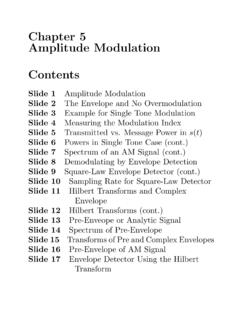
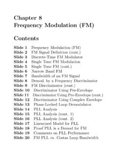
2 The reactions are two force of ConnectionIdealized SymbolNumber of UnknownsReactionFMTwo unknowns. The reactions are a force and unknowns. The reactions are the moment and the two (7)fixed support(5)Smooth pin or hinge(6)slider6 Idealized m4 mABactual structureidealized structure3 m4 mABF7idealized framing planABCD joistslabcolumngirderfixed-connected beamidealize beamfixed-connected overhanging beamIdealized beam8idealized framing planidealized framing plan9 Tributary beamgirderslabdeck girderpierveihicleslabstringerfloor beamgirder10wall footingslab on gradecolumnlandingstairsfoundationwallba sement1st floorsupported slab2nd floorbeambeamjoist slabjoistspread footingspandrelbeam11 ABCDEF idealized framing plan4 m4 m2 m2 kN/m2 One-Way midealized beam1 m1 m1 m1 m1 kN/m2 kN2 kNidealized girderFB2 m2 m2 kN1 kN1 kN12 ABCDEFI dealized framing planfor one-way slab actionrequires2/12 LLL2L1L1L1/2L1/2concrete slab isreinforced in two directions, poured on plane formsAgirderbeamcolumn136 m4 midealized framing planABCDL2/L1 = < 24 m4 midealized framing planABCDL2/L1 = 1 Two-Way m4 m4 kN/m245o45o2 m45o45o2 m2 mACidealized beam1 kN/m2 m2 mAB1kN/m2 m2 m 2 m2 m2 mABidealized beam, all1 kN/m2 m2 m1 kN/m14 Principle of Superposition P1d+Two requirements must be imposed for the principleof superposition to apply : 1.
3 The material must behave in a linear-elastic manner, so that Hooke s law is valid, and therefore the load will be proportional to displacement. = P/A = PL/AE 2. The geometry of the structure must not undergo significant change when the loads are applied, , small displacement theory applies. Large displacements will significantly changeand orientation of the loads. An example wouldbe a cantilevered thin rod subjected to a force at its P = P1 + P2d P2d15 Equations of Equilibrium Fx = 0 Fy = 0 Fz = 0 Mx = 0 My = 0 Mz = 0 Vinternal loadingsNMMNV16 Determinacy and Stabilityr = 3n, Statically determinater > 3n, Statically indeterminaten = the total parts of structure = the total number of unknown reactive force and moment components Determinacy17 Example 2-1 Classify each of the beams shown below as Statically Determinate or staticallyindeterminate. If Statically indeterminate, report the number of degrees ofindeterminacy. The beams are subjected to external loadings that are assumed tobe known and can act anywhere on the = 3, n = 1, 3 = 3(1) Statically determinater = 5, n = 1, 5 - 3(1) = 2 Statically indeterminate to the second degreer = 6, n = 2, 6 = 3(2) Statically determinater = 10, n = 3, 10 - 3(3) = 1 Statically indeterminate to the first degreehinge19 Example 2-2 Classify each of the pin-connected Structures shown in figure below as staticallydeterminate or Statically indeterminate.
4 If Statically are subjected to arbitraryexternal loadings that are assumed to be known and can act anywhere on = 7, n = 2, 7 - 3(2) = 1 Statically indeterminate to the first degreer = 9, n = 3, 9 = 3(3) Statically determinate21r = 10, n = 2, 10 - 6 = 4 Statically indeterminate to the fourthdegreer = 9, n = 3, 9 = 3(3) Statically determinate22 Example 2-3 Classify each of the frames shown in figure below as Statically Determinate orstatically indeterminate. If Statically indeterminate, report the number of degreesof indeterminacy. The frames are subjected to external loadings that are assumedto be known and can act anywhere on the = 9, n = 2, 9 - 6 = 3 Statically indeterminate to the third degreer = 15, n = 3, 15 - 9 = 6 Statically indeterminate to the sixth degree24 StabilityPartial ConstrainsAPPAMAFAr < 3n, unstable>r 3n, unstable if member reactions are concurrent or parallel or some of the components form a collapsible mechanism25 Improper ConstraintsPABCdOOPABCdFAFBFCABCPABCPFAF BFC26 Example 2-4 Classify each of the Structures in the figure below as stable or unstable.
5 Thestructures are subjected to arbitrary external loads that are assumed to be member is stable since the reactions are non-concurrent and is also Statically compound beam is stable. It is also indeterminate to the second compound beam is unstable since the three reactions are all member is unstable since the three reactions are concurrent at structure is unstable since r = 7, n = 3, so that, r < 3n, 7 < 9. Also, this canbe seen by inspection, since AB can move horizontally without of the Equations of EquilibriumABCDEP1P2 DxDyDxBxByBxByEyExExP2P1 AyAxCxr = 9, n = 3, 9 = 3(3); Statically determinate30 ABCP2P1BP2P1 AyAxCyCxP1P2 AyAxCyCxBxBxByr = 6, n = 2, 6 = 3(2); Statically determinate31 Example 2-5 Determine the reactions on the beam m1 m2 m70 kN m150 mAB32 SOLUTION+ MA = 0:By(4) - ( )(3) + ( )( ) -70 = 0 By = kN, Fy = 0:+Ay - + = 0 Ay = kN , Fx = 0:+Ax - = 0: Ax = kN , 3 m1 m70 kN mAyAxBy265 cos 60o = kN265 sin 60o = kN3 m1 m2 m70 kN m265 mAB33 Example 2-6 Determine the reactions on the beam kN/m5 kN/m12 m34 SOLUTIONA15 kN/m5 kN/m12 m Fx = 0:+Ax = 0 Fy = 0:+Ay - 60 - 60 = 0 Ay = 120 kN , + MA = 0:MA - (60)(4) - (60)(6) = 0 MA = 600 kN m12 m10 kN/m(1/2)(12)(10) = 60 kN4 m6 m(5)(12) = 60 kN5 kN/mAxAyMA35 Example 2-7 Determine the reactions on the beam shown.
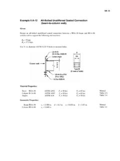
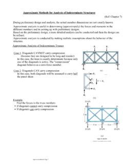
6 Assume A is a pin and the support atB is a roller (smooth surface).A3 m2 m4 m7 kN/mB36 SOLUTION+ MA = 0:-28(2) + NBsin (6) + NBcos (3) = 0 NB = kN Fx = 0:+Ax - NBcos = 0; Ax = = 8 kN , Fy = 0:+Ay - 28 + = 0 Ay = kN , tan-1(3/2) = = kN2 m6 m3 mA3 m2 m4 m7 kN/mB37 Example 2-8 The compound beam in figure below is fixed at A. Determine the reactions at A,B, and C. Assume that the connection at pin and C is a m4 m6 kN/m8 kN m388 kN mCyBxBy+ MA = 0:Member AB Fx = 0:+ Fy = 0:+MA - 36(3) + 2(6) = 0 MA = 96 kN mAx - B = 0 ; Ax = Bx = 0Ay - 36 + 2 = 0 Ay = 34 kN , BxAxAyMA36 kN3 m6 mByCy - By = 0; By = Cy = 2 kN , + MB = 0:Member BC Fx = 0:+ Fy = 0:+Cy(4) - 8 = 0 Cy = 2 kN , Bx = 0 SOLUTION hingeABC6 m4 m6 kN/m8 kN m39 Example 2-9 The side girder shown in the photo supports the boat and deck. An idealizedmodel of this girder is shown in the figure below, where it can be assumed A is aroller and B is a pin.
7 Using a local code the anticipated deck loading transmittedto the girder is 6 kN/m. Wind exerts a resultant horizontal force of 4 kN asshown, and the mass of the boat that is supported by the girder is 23 Mg. Theboat s mass center is at G. Determine the reactions at the m2 m4 mABCDG rollerpin404 mCDGByBx6( ) = mAy2 m23( ) kN = m+ MB = 0:6 m2 m4 mABCDGSOLUTION Fx = 0:+ Fy = 0:+4 - Bx = 0 Bx = 4 kN , ( ) -Ay(2) + ( ) -4( ) = 0 Ay = kN , + - + By = 0 By = 382 kN , rollerpin41 Example 2-10 Determine the horizontal and vertical components of reaction at the pins A, B,and C of the two-member frame shown in the figure kN2 m3 kN/mABC2 m2 m435426 kN1 m1 m8 kN2 mBxByAxAyCxCyBxBy Fy = 0:++ MA = 0:Member AB+ MC = 0:Member BC(3/5)8 SOLUTION Fx = 0:+Member BC Fx = 0:+ Fy = 0:+(4/5)8-By(2) +6(1) = 0 By = 3 kN , -8(2) - 3(2) +Bx( ) = 0 Bx = kN , Ax + (3/5)8 - = 0 Ax = kN , Cx - Bx = 0; Cx = Bx = kN , 3 - 6 + Cx = 0.
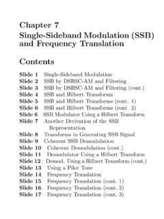
8 Cy = 3 kN , Ay - (4/5)8 - 3 = 0 Ay = kN , 8 kN2 m3 kN/mABC2 m2 m43543 Example 2-11-1 From the figure below, determine the horizontal and vertical components ofreaction at the pin connections A, B, and C of the supporting gable m3 m3 m3 m15 kN44 ABC3 m3 m3 m3 m15 kNSOLUTIONAxAyCxCy+ MA = 0:Entire Frame0)3(15)6(= yC Fy = 0:+ Ay + = 0Ay = kN , Cy = kN , 45BC3 m3 m3 kN AB3 m15 kNAx3 m3 kN BxByBxByMember BC Fx = 0:+ xC+ MB = 0:Member AB0)3( )6()3(15=++xA Fx = 0:+ + xB Fy = 0:+ + ByAx = kN , Bx = kN , By = kN= kN =Cx = kN462 m2 m3 m3 m4 m4 m3 m3 mwindABCE xample 2-11-2 The side of the building in the figure below is subjected to a wind loading thatcreates a uniform normal pressure of kPa on the windward side and a suctionpressure of kPa on the leeward side. Determine the horizontal and verticalcomponents of reaction at the pin connections A, B, and C of the supporting m2 m3 m3 m4 m4 m3 m3 mwindABCA uniform distributed load on the windward side is( kN/m2)(4 m) = 6 kN/mA uniform distributed load on the leeward side is( kN/m2)(4 m) = 2 kN/m6 kN/m6 kN/m2 kN/m2 kN/mABC3 m3 m3 m3 m48+ MA = 0:Entire frame Fy = 0:+B18 kN6 sin cos cos sin (18+6)( ) - ( + )cos 45o( ) - ( sin 45o)( )+ ( sin 45o)( ) + Cy(6) = 0 Cy = kN , Ay - sin 45o + sin 45o 3 + 24 = 0 Ay = kN496 cos sin 45 CxCy = kN18 kNAxAy= kN sin cos 45 AxBxByBxBy+ MB = 0:Member Fx = 0:+( sin 45o)( ) + ( 45o)( ) + (18)( ) + Ax(6) + 12(3) = 0 Ax = kN Fy = 0:+ Fx = 0.
9 +Member + cos 45o + 6 - Cx = 0Cx = kN , + 18 + cos 45o - Bx = 0Bx = kN , -12 - 45o + By = 0 By = kN , 50roof diaphragmfloor diaphragmABBAABABFA nalysis of Simple Diaphragm and shear Wall SystemsF/8F/8F/8F/8AF/8F/8AF/8F/8AF/8F/8 AF/8F/8F/2F/2F/8F/8F/8F/851 ABBACDCDWind Fsecond floor diaphragmshear wallsroof diaphragm2st floor1st floorroof diaphragmF/4F/4F/2F/16F/16AF/16F/16F/16F /163F/163F/163F/163F/163F/163F/16BF/16F/ 16F/16F/163F/163F/163F/163F/16F/4F/4F/4F /452 Example 2-12 Assume the wind loading acting on one side of a two-story building is as shownin the figure below. If shear walls are located at each of the corners as shown andflanked by columns, determine the shear in each panel located between the floorsand the shear along the m20 kPa3 m3 mABBACDCD4 m4 m53 SOLUTION30 m20 kPa3 m3 mABBACDCDFR1 = (103) N/m2 (20 m)(4 m) = 64 kNFR2 = (103) N/m2 (20 m)(4 m) = 96 kNFR1 /2 = 32FR2 /2 = 482st floor1st floorroof diaphragmFR1 /2 = 32 kN32 + 48 kNFR2 /2 = 48 kNF/8 = 12 kN12 kN12 kN12 kN12 kNA12 kN12 kN12 kN12 kN32 kN32 kN32 kN32 kN32 kN32 kN32 kN32 kN32 kN32 kNB40 kN40 kN40 kN40 kN4 m4 mFR1FR254 FvFv3 m4 m12 kN12 kN+ M = 0:Fv(3) - 12(4) = 0Fv = 16 kN+ M = 0:F v(3) - 32(4) = 0F v = kNF v3 m4 m32 kN32 kNF v