Transcription of Example II.A-12 All-Bolted Unstiffened Seated Connection ...
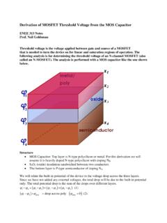
1 IIA-38. Example All-Bolted Unstiffened Seated Connection (beam-to-column web). Given: Design an All-Bolted Unstiffened Seated Connection between a W16 50 beam and W14 90. column web to support the following end reactions: RD = 9 kips RL = kips Use d-in. diameter astm A325-N bolts in standard holes. Material Properties: Beam W16 50 astm A992 Fy = 50 ksi Fu = 65 ksi Manual Column W14 90 astm A992 Fy = 50 ksi Fu = 65 ksi Table 2-3, Angles astm A36 Fy = 36 ksi Fu = 58 ksi Table 2-4. Geometric Properties: Beam W16 50 tw = in. d = in. tf = in. k = in. Manual Column W14 90 tw = in. Table 1-1. IIA-39. Solution: LRFD ASD. Ru = (9 kips) + ( kips) = 55 kips Ra = 9 kips + kips = kips Check beam web Check beam web Section J10. For local web yielding, For local web yielding, Ru R1 Ra R1 / Manual N min = k N min = k Table 9-4.
2 R2 R2 / . 55 kips kips kips kips = = kips kips = in. < in. = in. < in. = in. = in. For web crippling, For web crippling, N N. When When d d Ru R3 Ra R3 / . N min = N min =. R4 R4 / . 55 kips kips kips kips = =. kips kips which results in a negative quantity. which results in a negative quantity. N N. When > When > d d Ru R5 Ra R5 / . N min = N min =. R6 R6 / . 55 kips kips kips kips = =. kips/in. kips/in. which results in a negative quantity. which results in a negative quantity. Thus, N min = in. Thus, N min = in. IIA-40. Check shear yielding and flexural yielding Check shear yielding and flexural yielding of of angle. Check local yielding and angle. Check local yielding and crippling crippling of beam web of beam web Try an 8 in.
3 Angle length with a w in. Try an 8 in. angle length with a w in. Manual thickness and a 32 in. minimum outstanding thickness and a 32 in. minimum outstanding Table 10-5. leg. leg. Rn = 117 kips > 55 kips Rn / = kips > kips Try L6 4 w (4-in. OSL), 8-in. long with Try L6 4 w (4-in. OSL), 8-in. long with 52-in. bolt gage, Connection type B (four 52-in. bolt gage, Connection type B four bolts). bolts). For d-in. diameter astm A325-N bolts, For d-in. diameter astm A325-N bolts, Rn / = ( rn / ) n = kips > kips Manual Rn = v rn n = kips > 55 kips Table 10-5. Check bolt bearing on the angle Check bolt bearing on the angle Manual Bolt single shear strength = kips Bolt single shear strength = kips Table 7-1. and ( ) Section Rn = ( ) Rn / = Eqn (J3-6a).
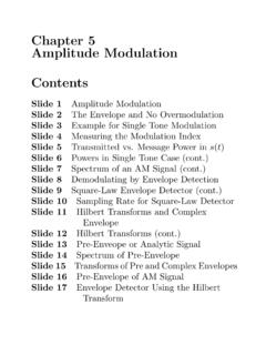
4 = ( )(7 8 in.)( 3 4 in.)(58 ksi) ( )(7 8 in.)( 3 4 in.)(58 ksi). =. = kips > kips = kips > kips Check supporting column Check supporting column Manual Bolt single shear strength = kips Bolt single shear strength = kips Table 7-1. and ( ) Section Rn = ( ) Rn / = Eqn (J3-6a).. ( )(7 8 in.)( in.)(65 ksi). = ( )(7 8 in.)( in.)(65 ksi) =. = kips > kips = kips > kips Select top angle and bolts Use an L4 4 4 with two d-in. diameter astm A325-N through each leg. IIA-44. Example Stiffened Seated Connection (beam-to-column flange). Given: Design a stiffened Seated Connection between a W21 68 beam and a W14 90 column flange, to support the following end reactions: RD = 21 kips RL = kips Use w in. diameter astm A325-N bolts in standard holes to connect the supported beam to the seat plate and top angle.
5 Use 70 ksi electrode welds to connect the stiffener and top angle to the column flange. Note: For calculation purposes, assume setback is equal to in. to account for possible beam underrun. Material Properties: Beam W21 68 astm A992 Fy = 50 ksi Fu = 65 ksi Manual Column W14 90 astm A992 Fy = 50 ksi Fu = 65 ksi Tables 2-3. Angles and plates astm A36 Fy = 36 ksi Fu = 58 ksi and 2-4. Geometric Properties: Beam W21 68 tw = in. d = in. tf = in. Manual Column W14 90 tf = in. Table 1-1. IIA-45. Solution: LRFD ASD. Ru = (21 kips) + ( kips) = 125 kips Ra = 21 kips + kips = kips Determine stiffener width W required Determine stiffener width W required For web crippling, assume N/d > For web crippling, assume N/d > Ru R5 Ra R5 / Manual Wmin = + setback Wmin = + setback Table 9-4.
6 R6 R6 / . 125 kips kips 3 kips kips 3. = + 4 in. = + 4 in. kips/in. kips/in. = in. = in. For local web yielding, For local web yielding, Ru R1 Ra R1 / . Wmin = + setback Wmin = + setback Manual R2 R2 / . Table 9-4. 125 kips kips 3 kips kips 3. = + 4 in. = + 4 in. kips/in. kips/in. = in. < in. = in. < in. Use W = 7 in. Use W = 7 in. Check assumption Check assumption N in. in. N in. in. = =. d in. d in. = > = > Determine stiffener length L and stiffener to Determine stiffener length L and stiffener to column flange weld size column flange weld size Try a stiffener with L = 15 in. and c in. Try a stiffener with L = 15 in. and c in. Manual weld weld Table 10-8. Rn = 139 kips > 125 kips Rn / = kips > kips Determine weld requirements for seat plate Use c-in.
7 Fillet welds on each side of the stiffener. Minimum length of seat-plate-to-column Manual flange weld is (L) = 3 in. If the weld between the seat plate and stiffener plate is required to Part 10. be stronger than the weld between the seat plate and the column flange, use c-in. fillet welds on each side of the stiffener to the seat plate, length of weld = 7 in. > 3 in. IIA-46. Determine the seat plate dimensions A width of 8 in. is adequate to accommodate two w-in. diameter astm A325-N bolts on a Manual 52 in. gage connecting the beam flange to the seat plate. Part 10. Use a PLa in. 7 in. 8 in. for the seat plate. LRFD ASD. Determine the stiffener plate thickness Determine the stiffener plate thickness Determine minimum plate thickness to Determine minimum plate thickness to Manual develop the stiffener-to-seat-plate weld.
8 Develop the stiffener-to-seat-plate weld. Section 10. tmin = 2w = 2(c in.) = s in. tmin = 2w = 2(c in.) = s in. Determine minimum plate thickness for a Determine minimum plate thickness for a stiffener with Fy = 36 ksi and beam with Fy = stiffener with Fy = 36 ksi and beam with Fy =. 50 ksi. 50 ksi. 50 50 50 50. tmin = tw = ( in.) tmin = tw = ( in.). 36 36 36 36. = in. < s in. = in. < s in. Use a PL s in. 7 in. 15 in. Use a PL s in. 7 in. 15 in. Check column web thickness D (5)(2). tw min = = = in. Fu 65. tw for W14 90 = in. LRFD ASD. in. Rn in.. Rn = 139 kips = kips . in. in.. = 129 kips > 125 kips = kips > kips Select top angle, bolts, and welds Use a L4 4 4 with two w in. diameter astm A325-N bolts through the supported-beam leg Section of the angle.
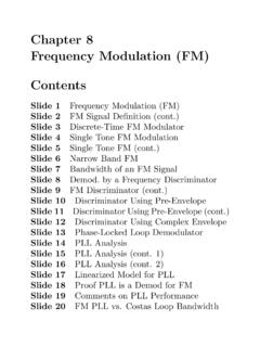
9 Use a x in. fillet weld along the toe of the supported leg of the angle. IIA-47. Example Stiffened Seated Connection (beam-to-column web). Given: Design a stiffened Seated Connection between a W21 68 beam and a W14 90 column web to support the following beam end reactions: RD = 21 kips RD = kips Use w in. diameter astm A325-N bolts in standard holes to connect the supported beam to the seat plate and top angle. Use 70 ksi electrode welds to connect the stiffener and top angle to the column web. Material Properties: Beam W21 68 astm A992 Fy = 50 ksi Fu = 65 ksi Manual Column W14 90 astm A992 Fy = 50 ksi Fu = 65 ksi Tables 2-3. Angles and plates astm A36 Fy = 36 ksi Fu = 58 ksi and 2-4. Geometric Properties: Beam W21 68 tw = in.
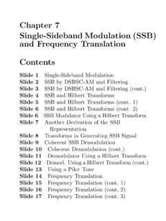
10 D = in. tf = in. Manual Column W14 90 tw = in. Table 1-1. IIA-96. Example Bolted/Welded Tee Connection (beam-to-column flange). Given: Design a tee Connection bolted to a W16 50 supported beam and welded to a W14 90. supporting column flange, to support the following beam end reactions: RD = 6 kips RL = 18 kips Use w in. diameter astm A325-N bolts in standard holes and E70 electrode welds. Try a WT5 with four-bolts. Material Properties: W16 50 astm A992 Fy = 50 ksi Fu = 65 ksi Manual W14 90 astm A992 Fy = 50 ksi Fu = 65 ksi Table 2-3. WT5 astm A992 Fy = 50 ksi Fu = 65 ksi Geometric Properties: Beam W16 50 tw = in. d = in. tf = in. Manual Column W14 90 tf = in. Tables 1-1. Tee WT5 d = in. bf = in. tf = in. and 1-8. ts = in. k1 = m in.