Transcription of Analytical method Validation: ICP-OES
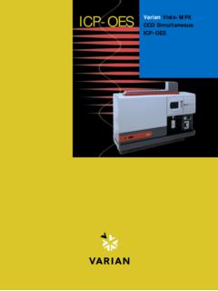
1 Prepared by Jonathan FitzsimmonsAnalytical method validation : ICP-OESP urpose: The following is a summary of tests/experiments performed to validate the ICP-OES instrument and establish an analysis method for samples. Instrument description: The instrument Inductively Coupled Plasma-Optical Emission Spectroscopy ( ICP-OES ) is used in atomic spectroscopy, and during analysis the sample is decomposed by intense heat into a cloud of hot gases containing free atoms and ions of the element(s) of interest. The high temperatures cause significant amounts of collisional excitation and ionization of the sample atoms. Once the atoms or ions are in their excited state, they can decay to lower states through thermal or radiative (emission) energy transitions. During ICP-OES analysis the intensity of the light emitted at specific wavelengths is measures and used to determine the concentration of the element(s) of interest.
2 In ICP-OES analysis the thermal excitation sources can populate a large number of different energy levels for several different elements at the same time. All of the excited atoms and ions can then emit their characteristic radiation at the same time. This results in the flexibility to choose from several different emissions concurrently and allows detection of multiple elements concurrently. Instrument IQ/OQ/PQ The installation qualification (IQ), operational qualification (OQ), and performance qualification (PQ) were complete by a Perkin Elmer service engineer on March 13, 2012. The instrument/system acceptance was completed on March 15, 2012 by a Perkin Elmer service engineer. The data and information associated with the studies are kept in the ICP-OES Instrument System log book which is kept by the ICP-OES . Performance ExperimentsPerformance experiments are periodically conducted to check instrument performance and/or Analytical method to test instrument performance are required by Perkin Elmer to obtain accurate data by the instrument during an analysis.
3 These tests use Perkin Elmer solutions and may or may not include elements of interests to the BNL isotope production group. Some of the tests were performed at instillation, while other tests were performed after modification of the instrument by Perkin Elmer service engineer. Results of the instrument performance tests can be found in the ICP-OES Instrument System log to test the Analytical method performance are recommended by the FDA in the document Guidance for Industry: Bioanalytical method validation . The experiments use elements of interest to the BNL isotope production group. Results from Analytical method performance experiments can be found in the ICP-OES Instrument System log book, and/or chapter 19 of the OPM s under ICP-OES . Other performance testing such as QC sample analysis is performed with every batch of product and the results are in batch files for the product.
4 Experimental summary: Instrument PerformanceElectronicSupplementaryMateri al(ESI) TheRoyalSocietyofChemistry2015 Prepared by Jonathan FitzsimmonsThe following performance tests are conducted by a Perkin Elmer service engineer to check the instrument performance: Align View, Detector Calibration, UV/Vis Wavelength Calibration, Precision, Spectral Resolution, Detection Limits and Stability. The results are recorded by the Perkin Elmer service engineer and kept in the ICP-OES Instrument System log instrument performance tests are conducted by BNL staff prior to conducting experiments to test Analytical method performance or setting up selectivity (emission wavelengths). The following ICP-OES instrument performance testes were/should be performed within 1 week of the studies: Detector Calibration, Align View, UV/Vis Wavelength Calibration. For tests utilizing the plasma the tubing at the peristaltic pump should be changed if there is more than 10 hours of operating time on them.
5 It is important that the instrument be operated with the plasma on for at least 30 minutes pumping water on both internal standard and sample lines before initiating the align view and wavelength calibration. The results for instrument performance tests should be kept in the ICP-OES Instrument System log Calibration Purpose: This procedure is an electronic calibration for the instrument detectors. Start the ICP according to OPM ICP-OES Operation Model Optima 7300 DV. In the Tools menu, click on Spectrometer Control. The Spectrometer Control window appears. Click on Detector Calibration in the Spectrometer Control window to display the Detector Calibration dialog. Click on OK to begin Detector Calibration. The system automatically closes the shutter to measure signal bias and dark current. The detector calibration routine may take up to twenty minutes.
6 This test can be performed with or without the plasma on. Align View Purpose: This procedure automatically aligns the torch viewing position for the highest signal intensity. Solutions you will need: A standard solution containing 1 ppm Mn for the axial view alignment. A standard solution containing 10 ppm Mn for the radial view alignment. In the Tools menu, click on Spectrometer Control. The Spectrometer Control window appears. First do the alignment in the Axial viewing mode, then select the Radial viewing mode and repeat the procedure. To view spectra collected during the procedure, open the Spectra Display window. Click on Align View in the Spectrometer Control window. Using this dialog box: Click on the Select Analyte option and then select Manganese, which is typically used as the alignment wavelength for the majority of analyses. Set the Read Delay time.
7 Aspirate a solution containing 1 ppm Mn solution for the axial and 10 ppm Mn for the radial view. The system will determine the intensity at the selected wavelength, while adjusting the viewing position in incremental steps. Prepared by Jonathan FitzsimmonsUV/Vis Wavelength CalibrationPurpose: The process of determining the relationship between the physical settings of a spectrometer and the wavelengths at which it takes a You will Need: Calmix 3 solution (Part No. N058-2152) available through PerkinElmer, which contains 100 mg/L of P, K, S; and 20 mg/L of As, La, Li, Mn, Mo, Ni, Sc, Na. For spectrometers that have a visible wavelength channel on the detector, you will need VIS Wavecal mix (Part No. N930-2946) available through PerkinElmer, which contains 1 mg/mL Ba, Ca; and 10 mg/L of La, Li, Mn, Na, Sr; and 50 mg/L of K. Rinse solutionTo initiate a wavelength calibration1.
8 Make sure that the plasma is lit and has been on for at least one hour on Optima In the Tools menu, click on Spectrometer Spectrometer Control window perform UV channel wavelength calibration: Aspirate the Calmix 3 solution (Part No. N058-2152 Perkin Elmer). On Axial (XL) instruments, you may need to dilute the wavecal solution 1:10 to keep certain emission lines from saturating the detector. On Dual View (DV) instruments, select Radial viewing. If you have selected axial, a message appears informing you to change to radial. Select UV, then click on Wavelength Calibration in the Spectrometer Control window. In the dialog that appears, click on OK to perform the calibration. The UV calibration may take several minutes. You may view the spectra used for calibration by clicking on Spectra in the toolbar. When the UV calibration is complete, the UV coefficients and RMS (Root Means Square) value will be displayed in the Results window.
9 These values should meet the following specifications:UV Coefficients and RMSS pecificationFirst CoefficientAbsolute value < CoefficientAbsolute value < CoefficientAbsolute value < variability of wavelength offsets)< these specifications are not met, repeat the wavelength calibration and make sure all peaks can be seen in the Spectra Display window. If the specifications are still not met, a complete optical alignment may be required. Contact your PerkinElmer service spectrometers that have a visible wavelength channel on the detector, to perform VIS channel wavelength calibration:Prepared by Jonathan FitzsimmonsAspirate VIS Wavecal mix (Part No. N930-2946). On Axial (XL) instruments, you may need to dilute the wavecal solution 1:10 to keep certain emission lines from saturating the detector. On Dual View (DV) instruments, select Radial viewing.
10 If you have selected axial, a message appears informing you to change to radial. Select VIS, then click on Wavelength Calibration in the Spectrometer Control window. The VIS calibration may take several minutes. You may view the spectra used for calibration by clicking on Spectra in the toolbar. When the VIS calibration is complete, the VIS coefficients and RMS (Root Means Square) value will be displayed in the Results window. These values should meet the following specifications. VIS Coefficients and RMSS pecificationFirst CoefficientAbsolute value < CoefficientAbsolute value < CoefficientAbsolute value < variability of wavelength offsets< these specifications are not met, repeat the wavelength calibration and make sure all peaks can be seen in the Spectra Display window. If the specifications are still not met, a complete optical alignment may be required.


