Transcription of ANALYTICAL OPTIMIZATION OF SIMPLE ROOF SHADING …
1 ANALYTICAL OPTIMIZATION OF SIMPLE roof SHADING DEVICES Khaled Nassar1and Mohamed Aly1 1 The American University in Cairo line below should be left ABSTRACT Parametric and algorithmic design tools have developed significantly in the last few years with the advent of several commercial and open-source applications and simulation software. These tools have been used extensively in the design and analysis of various building elements such as glazing, screens, massing and SHADING devices. Typically, ether iterative, parametric or OPTIMIZATION techniques are coupled with simulation software to reach an optimum design for the considered element. Setting up these problems usually requires time and effort, but sometime the designers need a SIMPLE tool to design particular elements.
2 This paper presents an analytic approach for designing SIMPLE roof SHADING devices. The proposed approach is based on a ground-up analysis of the SHADING device geometry to reach global optimum designs for the elements. The approach is applied to a SIMPLE roof SHADING element and it is shown how different objectives and situations can be modelled using this approach. The results are compared to ENERGY PLUS simulations to verify the results. It is shown that comparable results can be achieved with the proposed approach without the need for the numerical simulation and in less time. INTRODUCTION In warm climates it is often important to protect of the building from unwanted solar gain as a key part of any cooling strategy which is most readily achieved by blocking the sun s rays before they reach the building (R.)
3 Mc Cluney, 1990). It has been shown repeatedly that concrete roof slabs without thermal insulation lead to thermal stress resulting in negative effects on the thermal comfort of the occupants (Garde et al,. 2005). Effective SHADING is an excellent option for controlling solar radiation and reducing the amount of heat gain in buildings. By blocking both the direct and diffuse solar radiation they offer great passive potential in hot environments where cooling loads are significant, while movable SHADING addresses nocturnal radiation in night hours A number of publications addressed the effect of SHADING wall openings, such as windows, on energy consumption (Sherif et al.
4 , 2011), while other publications examine the dependence of the thermal loads reduction on the size of solar SHADING systems (Franzetti et al., 2004), (Afnor, 2003) and (Kuhn et al., 2000). Garde (2005) provides a comprehensive list of various research efforts on designing SHADING devices. Liangliang et al 2012 investigated the rotation of an integrated solar panel (BIPV) in a SHADING device in Hong Kong. In order to maximize the energy generated while reducing the solar radiation different tilt angles were explored. The simulation results showed that the SHADING device BIPV did significantly increase the total energy benefits relative to PV modules.
5 Niccol et al (2012) developed an algorithm to design a dynamic solar SHADING system for an office building situated in Milan, Italy. The study aimed to define the ANALYTICAL method for defining the optimal movement profile for dynamic SHADING system based on the horizontal mobile blinds for indoor visual comfort. This study allowed to define the annual movement of SHADING devices, to customize the behaviour of every single SHADING device and ensure constant control of their movements. In addition a wide range of simulation tools can be used to assess the effect of SHADING on the various aspects of the building. These tools often require a detailed building input and some will have a significant run time.
6 While these may be of importance in many situations, it is often the case where the designers need a SIMPLE tool to design a particular building element. Therefore, often a fully fledged simulation is not warranted and a SIMPLE design tool (in the form of a spreadsheet or an add-on) may be required. Although the many previous research efforts addressed the issue of SHADING devices for windows, design of roof SHADING devices has not received an equal amount of attention. The work presented here addresses this gap and tries to develop a tool for the design of SIMPLE roof SHADING devices (RSD). The goal is to design a SIMPLE tool with a user friendly interface to globally optimize very SIMPLE typologies of the RSD.
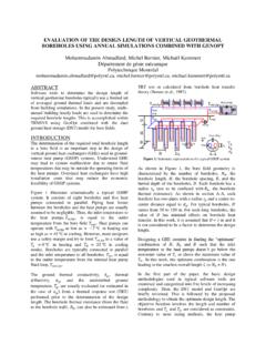
7 In the next section a formulation of the RSD problem is presented. Proceedings of BS2013: 13th Conference of International Building Performance Simulation Association, Chamb ry, France, August 26-28- 419 - Figure 1, Samples of SIMPLE roof shades PROBLEM FORMULATION Often problems related to OPTIMIZATION of SHADING devices can be formulated analytically from the ground up by considering the geometry of the SHADING device and the building. In general, most SHADING devices try to minimize the amount of direct solar radiation falling on the building surface. Since the solar beam has a known direction, it is often possible to model such problems by considering the amount of SHADING the device will render on the building surface.
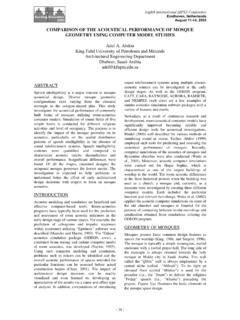
8 This shaded area can be formulated as a function in the design of the SHADING device and the solar angles (azimuth and altitude) given a particular time. Then the total shaded area throughout the year can be calculated by integrating that function over the hours of the day and over the all the days in the year. Figure 2, The main variables in the problem; s is the spacing between the center lines of the SHADING GHYLFHV G LV WKH OHQJWK RI WKH VKDGLQJ GHYLFH LV WKH pitch angle. SIMPLE roof shades are defines as an array of linear rectilinear SHADING elements placed in a plane parallel to the roof with each element perpendicular to the roof plane. Samples of this SIMPLE configuration are shown in figure 1.
9 The main goal is WR PD[LPL]H WKH ,QVWDQWDQHRXV 6 KDGLQJ )DFWRU W GXH WR WKH SUHVHQFH RI WKH 56' W FDQ EH GHILQHG as the ratio of the global solar radiation (direct, diffuse and reflected) received on the roof in presence of SHADING devices to the global solar radiation which would be received on the roof without the RSD. However, since we usually set up OPTIMIZATION as a minimization problem we will take the UHFLSURFDO RI WKH W DV GHILQHG E\ ( )= + + ( ) + ( ) + (1) Where, FS (t) is the instantaneous SHADING factor for direct radiation; FS is the instantaneous SHADING factor for diffuse radiation; I ,I ,I are the direct, diffuse and reflected solar irradiance respectively falling on the roof plane window without the RSD installed.
10 In this case, obviously no ground reflected component is considered. Since we assume that I +I +I are constant regardless of roof orientation (in the case of no obstructions), the main goal not become to maximize FS (t) and FS (t). Figure 2, shows the different variables in the problem. Consider first the situation where the RSD is oriented in along the West-East orientation with all the louvers in the RSD being of unit length ( d =1) and a sufficiently large roof shaded area such that all the shadow falls on the roof . In this case the FS (t) Proceedings of BS2013: 13th Conference of International Building Performance Simulation Association, Chamb ry, France, August 26-28- 420 -can be simply by (given by triangles ABC in figure 2), FS (t) = (| ( ) |) ( ( )) (2) :KHUH (t) is the projected solar altitude angle at WLPH W DQG 3 LWFK DQJOH RI VKDGLQJ GHYLFH ZLWK WKH horizontal plane.