Transcription of Antenna Patterns and Their Meaning - Industrial Networking
1 White Paper All contents are Copyright 1992 2007 Cisco Systems, Inc. All rights reserved. This document is Cisco Public Information. Page 1 of 17 Antenna Patterns and Their Meaning Much can be learned about how an Antenna performs from its Patterns . This paper describes many of the common Antenna parameters that can be understood from the Patterns . Introduction A major component of a wireless LAN system is the Antenna . There are several different types and they all have Their place. However, there can be some confusion surrounding the language used to specify antennas as well as the basic function of each type of Antenna . The purpose of this white paper is to dispel the confusion surrounding antennas and Their function. This document is not meant to be an electromagnetic primer nor a deployment guide.
2 Rather, it should be used as a dictionary of basic antennas and Antenna terminology as well as a tutorial specifically covering Antenna Patterns and the parameters associated with those Patterns . The focus is on many of the various antennas that might be encountered in a wireless LAN system. We begin with a glossary of basic definitions and then progress through a discussion of some common Antenna types and Their properties. Along the way, the Antenna Patterns are shown and explained, including the 3-D radiation pattern from the antennas. Typical performance from each Antenna type is described as well. Of course, there are plenty of exceptions to the typical Antenna , as many Antenna types can be designed to enhance one or more parameters. But it is often helpful to see a few examples and have some of these parameters highlighted.
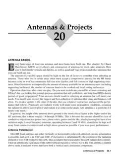
3 In a WLAN system, commonly used antennas are dipoles, omnidirectional antennas, patches and Yagis. These antennas are shown in Figure 1. Although these Antenna packages might vary somewhat from one manufacturer to another, these are typical packages for these types of antennas. The function of each of these Antenna types is explained in some detail in this paper. Figure 1. Various Antennas Commonly Found in WLAN Systems White Paper All contents are Copyright 1992 2007 Cisco Systems, Inc. All rights reserved. This document is Cisco Public Information. Page 2 of 17 Historical Note: The Antenna type that we commonly refer to as a Yagi was first developed in the late 1920 s by two professors, Shintaro Uda and Hidetsugu Yagi at Tohoku University in Japan. While the Antenna was mainly developed by Uda, Professor Yagi popularized the Antenna design in the US and elsewhere through various conference presentations.
4 Yagi s name has been associated with this Antenna type since that time. Basic Definitions We often define antennas and Antenna terminology in terms of a transmitting Antenna , but all the definitions apply to receiving antennas as well. In fact, an Antenna s properties are the same in either operating mode. So, whether it is stated or not, all the definitions and descriptions describe antennas that are either part of a transmitter or a receiver. Antenna . An Antenna is a transducer between a guided wave and a radiated wave, or vice versa. The structure that guides the energy to the Antenna is most evident as a coaxial cable attached to the Antenna . The radiated energy is characterized by the Antenna s radiation pattern. Antenna pattern. The radiation pattern or Antenna pattern is the graphical representation of the radiation properties of the Antenna as a function of space.
5 That is, the Antenna s pattern describes how the Antenna radiates energy out into space (or how it receives energy). It is important to state that an Antenna radiates energy in all directions, at least to some extent, so the Antenna pattern is actually three-dimensional. It is common, however, to describe this 3D pattern with two planar Patterns , called the principal plane Patterns . These principal plane Patterns can be obtained by making two slices through the 3D pattern through the maximum value of the pattern or by direct measurement. It is these principal plane Patterns that are commonly referred to as the Antenna Patterns . Characterizing an Antenna s radiation properties with two principal plane Patterns works quite well for antennas that have well-behaved Patterns that is, not much information is lost when only two planes are shown.
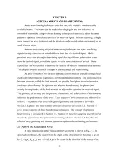
6 Figure 2 shows a possible coordinate system used for making such Antenna measurements. Figure 2. Antenna Measurement Coordinate System White Paper All contents are Copyright 1992 2007 Cisco Systems, Inc. All rights reserved. This document is Cisco Public Information. Page 3 of 17 In discussions of principal plane Patterns or even Antenna Patterns , you will frequently encounter the terms azimuth plane pattern and elevation plane pattern. The term azimuth is commonly found in reference to the horizon or the horizontal whereas the term elevation commonly refers to the vertical . When used to describe Antenna Patterns , these terms assume that the Antenna is mounted (or measured) in the orientation in which it will be used. In Figure 2, the x-y plane ( = 90 deg) is the azimuth plane.
7 The azimuth plane pattern is measured when the measurement is made traversing the entire x-y plane around the Antenna under test. The elevation plane is then a plane orthogonal to the x-y plane, say the y-z plane ( = 90 deg). The elevation plane pattern is made traversing the entire y-z plane around the Antenna under test. The Antenna Patterns (azimuth and elevation plane Patterns ) are frequently shown as plots in polar coordinates. This gives the viewer the ability to easily visualize how the Antenna radiates in all directions as if the Antenna was aimed or mounted already. Occasionally, it may be helpful to plot the Antenna Patterns in Cartesian (rectangular) coordinates, especially when there are several side lobes in the Patterns and where the levels of these side lobes are important.
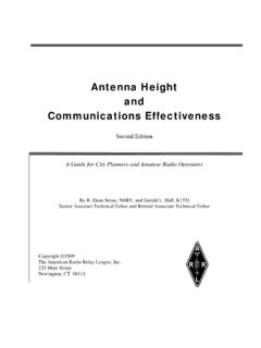
8 Lobes. Any given Antenna pattern has portions of the pattern that are called lobes. A lobe can be a main lobe, a side lobe or a back lobe and these descriptions refer to that portion of the pattern in which the lobe appears. In general, a lobe is any part of the pattern that is surrounded by regions of relatively weaker radiation. So a lobe is any part of the pattern that sticks out and the names of the various types of lobes are somewhat self-explanatory. Figure 3 provides a view of a radiation pattern with the lobes labeled in each type of plot. Figure 3. Radiation Patterns in Polar and Cartesian Coordinates Showing Various Types of Lobes Isotropic radiator. An isotropic radiator is a hypothetical lossless Antenna that radiates its energy equally in all directions. This imaginary Antenna would have a spherical radiation pattern and the principal plane cuts would both be circles (indeed, any plane cut would be a circle).
9 Gain. The gain of an Antenna (in any given direction) is defined as the ratio of the power gain in a given direction to the power gain of a reference Antenna in the same direction. It is standard practice to use an isotropic radiator as the reference Antenna in this definition. Note that an isotropic radiator would be lossless and that it would radiate its energy equally in all directions. That means that the gain of an isotropic radiator is G = 1 (or 0 dB). It is customary to use the unit dBi (decibels relative to an isotropic radiator) for gain with respect to an isotropic radiator. Gain expressed in dBi is computed using the following formula: White Paper All contents are Copyright 1992 2007 Cisco Systems, Inc. All rights reserved. This document is Cisco Public Information.
10 Page 4 of 17 GdBi = 10*Log (GNumeric/GIsotropic) = 10*Log (GNumeric) Occasionally, a theoretical dipole is used as the reference, so the unit dBd (decibels relative to a dipole) will be used to describe the gain with respect to a dipole. This unit tends to be used when referring to the gain of omnidirectional antennas of higher gain. In the case of these higher gain omnidirectional antennas, Their gain in dBd would be an expression of Their gain above dBi. So if an Antenna has a gain of 3 dBd it also has a gain of dBi. Note that when a single number is stated for the gain of an Antenna , it is assumed that this is the maximum gain (the gain in the direction of the maximum radiation). It is important to state that an Antenna with gain doesn t create radiated power. The Antenna simply directs the way the radiated power is distributed relative to radiating the power equally in all directions and the gain is just a characterization of the way the power is radiated.