Transcription of Appendix 8: Timber Frame Detailing
1 Appendix 8: Timber Frame Detailing This Appendix illustrates with typical details major design and construction issues, which must be considered when using a Timber Frame approach. The details shown are not intended to exclude other approaches but are currently accepted good practice. Alternative approaches should be proven by way of appropriate certification to be appropriate for their conditions of use. Timber Frame separation walls (party walls ) Separating party walls should be constructed to provide the required structural stability, acoustic performance and fire resistance. Clearly detailed technical drawings and TGDs will facilitate proper construction. Drawings should be readily available to verify compliance with the relevant Building Regulations by all responsible bodies or independent third party approval bodies.
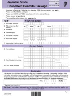
2 The annotated diagram in Fig illustrates best practice in Detailing Timber Frame party walls . With regard to maintaining 60 minutes fire resistance with Timber Frame party walls the drawings prepared by the designer/manufacturer must provide support for plasterboard fixings at: Top, bottom and vertical edges of plasterboard Intermediate supports Wall junctions Ceiling of intermediate/party floors which are adjacent to party walls Ceiling of top floors which are adjacent to party walls Service penetrations in party wall plasterboard Party wall stud location and internal wall and party wall junction Where the party wall separates two dwellings, hard contacts between the dwellings can lead to failure of the wall s required acoustic performance. The builder must ensure that all bracing and all off-cuts have been removed following erection.
3 Good site quality control and erector crew knowledge can prevent the occurrence of performance failure. Appendices A Figure Typical 60-minute 2 storey separating wall with attic space illustrating current good practice in Timber Frame construction. SECTION DETAIL (not to scale) Appendices Services Installations at Timber Frame Party Wall Construction Installing services within a party wall is not permitted in Scotland. This is overcome by installing the services between the party wall and an internal dummy wall. While this may satisfy concerns regarding fire resistance, it does not address occupier perceptions. The dummy wall may give the occupier a sense that the walls are not robust and issues may arise with regard to hanging shelves or heavy furnishings such as mirrors.
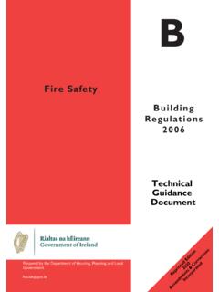
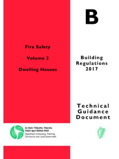
4 Figure An alternative battened out services void can be used where services cannot be avoided at party walls . The services are installed in the void and the party wall proper is left with no penetrations or services. PLAN DETAIL (not to scale) Services are not permitted in Timber Frame separating (party wall) walls in Ireland. Services must therefore be carefully thought out and should avoid the party wall. If this is impossible an alternative is to construct a services void in adding to the party wall construction (see figure ). Appendices 60-Minute Party Wall Junction with Load-Bearing External Wall Adequate Timber support for plasterboard fixings is essential when providing 60 minutes, fire resistance between dwellings and required fire resistance to load-bearing walls . The doubling up of studs and the use of 140 mm L-type corners is recommended by the Consortium.
5 L-type corners also provide the insulation installers with open access to junctions and/or corners, which helps minimise sound transfer and cold bridging. Figure Typical Timber Frame 60-minute separating wall junction with Timber Frame external wall and masonry cladding. PLAN DETAIL (not to scale) Appendices Party Wall with Trusses Running Perpendicular to Party Wall To ensure 60 minutes, fire resistance between dwellings when trusses run 90 degree to party walls , the Consortium recommends that truss ends be supported by a girder, not the party wall. This girder truss may have multiple pitches and/or a flat top section but will ensure that the plasterboard is not penetrated (see figure ) Figure Typical detail of a 60-minute separating wall where perpendicular to Timber roof trusses.
6 SECTION DETAIL (not to scale) Appendices Appendices Chimneys Adjacent to Party walls To ensure 60 minutes, fire resistance and compliance with acoustic requirements between dwellings where chimneys are bordering on party walls , acoustic insulation and plasterboard can be installed at party walls adjacent to the chimney before the installation of the chimney. This is not that dissimilar to stairwell/staircase and spandrel panel details. Double trimmer joists should be installed to support party walls and to provide 60 minutes, fire resistance at floor zones. On using this detail, the chimney will not penetrate the plasterboard and will be located approximately 184 mm from the centre of the party wall cavity (see figures and ). The installation of the plasterboard and all fire stopping and insulation must be confirmed prior to installation of the fireplace and flue construction.
7 This is an important site quality control issue. Figure Fireplace installation allowing continuous party wall construction can be used as an alternative to a back to back fireplace installation. Note that this will take more space within the room. PLAN DETAIL (not to scale) Figure Flue installation allowing continuous party wall construction can be used as an alternative to a back to back fireplace installation. Note that this will take more space within the room. PLAN DETAIL (not to scale) Open Deck Balcony Details Prevention of moisture ingress into structural timbers is paramount in open deck balcony Detailing . Lead work guarantees moisture protection and is recommended by the Consortium when Detailing an open deck balcony. Cantilevered joists must be dropped below final floor level and lead work must return under all door openings to prevent moisture ingress.
8 Detailing of breather membrane and lead work junction is as typical but care must be taken not to restrict ventilation to Timber and/or external wall cavity ; drainage of external wall cavity must also be maintained (see Figure ). The durability of this type of detail is suspect due to its complexity and potential for failure. Figure Typical open deck Timber Frame balcony detail. SECTION DETAIL (not to scale) Appendices Closed Deck Balcony Prevention of moisture ingress into structural timbers is paramount in closed deck balcony Detailing . An appropriate roof covering guarantees moisture protection and the use of duckboards will offer a durable deck surface. The Consortium recommends both. Cantilevered joists must be dropped below final floor level and roof covering must return under all door openings to prevent moisture ingress.
9 Detailing of breather membrane and floor covering junction is as typical but care must be taken not to restrict ventilation to Timber and/or external wall cavity ; drainage of external wall cavity must also be maintained (see figure ) Figure Typical closed deck Timber Frame balcony detail. SECTION DETAIL (not to scale) Appendices Balcony at Penthouse Wall Section Load transfer and tie down of penthouses can be equated to roof design and will require structural load transfer from the top down. Penthouse load- bearing walls may need to be designed as truss walls if load transfer is localised. Detailing of breather membrane and roof covering junction is as typical but care must be taken not to restrict ventilation to Timber and/or external wall cavity ; drainage of external wall cavity must also be maintained (see Fig ).
10 Figure Typical closed deck Timber Frame balcony detail at a penthouse level. The finish deck material may vary and should be installed in accordance with the manufacturer s requirements and the requirements of the roofing manufacturer. SECTION DETAIL (not to scale) Appendices Differential Movement in Mid-Rise construction Timber responds to changes in humidity by expanding or contracting across its grain. A 38 mm thick Timber sole plate can expand by 1 mm, a 241 mm solid Timber joist by 6 mm. The key to reducing differential movement is to design out the horizontal cross grain and use manufactured Timber products that do not have a grain running in one direction. Sole plates, solid Timber joists, solid Timber lintels, top and bottom rails are all typical examples of horizontal cross grain Timber in a structure.