Transcription of APPENDIX B - Voltage Multipliers, Inc.
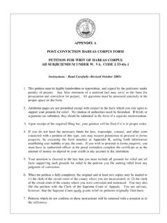
1 APPENDIX B. Diode Thermal Analysis Controlling junction temperature is key to reliable semiconductor package design. High Voltage diodes present unique junction temperature problems which must be addressed. In high Voltage diodes, heat is generated primarily by: 1) Forward Voltage 2) Reverse Leakage Current 3) Reverse Recovery Losses Each of these factors change differently and must be considered carefully over the intended operating range. The following examples depict the typical relative change in heat sources: Diode Losses vs. Temperature: Diode= 1N6515. TRR= 70ns PIV= 3000V. VF = @ Circuit Conditions: Operating Frequency = 50kHz Voltage Rise Time = 100ns Average Rectified Current = per diode Reverse Voltage = 2000V Peak TJ = +25 C TJ = +75 C TJ = +125 C.
2 Heat Source Heat Source Heat Source 14. VF watts VF watts VF watts IR watts IR watts IR watts TRR watts TRR watts TRR watts Total watts Total watts Total watts 305. APPENDIX B: Diode Thermal Analysis Controlling Junction Temperature In the previous example, the junction temperature would exceed +150 C, if the package thermal impedance exceeds C/watt. Thus, total heat source con- sideration is necessary. The deceptive difference, in high Voltage application recovery losses, is primarily a result of the high Voltage bias, as applied while the diode is recovering from forward bias to a blocking mode. The problem pre- sented can be addressed by: a) decreasing the forward Voltage b) decreasing the reverse recovery losses c) improving the thermal impedance d) operating over a reduced temperature range Both forward Voltage and reverse recovery losses are dependent on the diode used in the circuit, as well as the circuit characteristics.
3 In many cases, there are trade-offs to any change made in diode characteristics. For instance, decreasing the reverse recovery time in a diode will generally cause its forward Voltage to increase. However, reducing a diode's reverse blocking Voltage in order to facili- tate a reduction in its forward Voltage may increase the risk of exceeding the Voltage rating on the part. Once a diode has been selected for an application, it is necessary to optimize the thermal impedance of the diode package. Rectifier thermal impedance is the resistance against heat energy movement, from the rectifier junction to a heat sink or heat dissipation reservoir. The thermal path for the rectifier will vary de- pending on the part's packaging configuration.
4 The remainder of APPENDIX B will list some typical rectifier packaging schemes to address these issues. Reverse Recovery Power Loss Measurement In high Voltage , high frequency diode applications, reverse recovery losses can significantly contribute to the power dissipated in the diodes. Reverse recovery losses occur during the transition from forward current to reverse Voltage . When reverse Voltage is applied to a diode, it will conduct in the reverse direction for a short time (the reverse recovery time). While the diode is conducting in the re- verse direction, the power dissipated is equal to the reverse recovery 306. APPENDIX B: Diode Thermal Analysis Reverse Recovery Power Loss Measurement (continued).
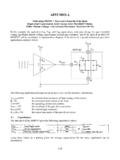
5 Current multiplied by the reverse Voltage . Unfortunately, it is not possible to determine the reverse recovery losses for a diode in a circuit without actually testing the circuit. While the reverse recovery time rating of a diode gives a relative indication of its speed, the rating is based on controlled laboratory conditions. In an actual circuit, the conditions which affect reverse recovery time, such as forward operating current, dv/dt of the volt- age waveform, reverse Voltage , and termperature, can vary considerably. The best way to evaluate reverse recovery losses is to monitor diode current and reverse Voltage waveforms while the diode is operating in the circuit. Figure 1.
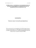
6 Shows waveforms for a simulated circuit. The Voltage waveform shows a peak reverse Voltage of 2400V and a nominal reverse Voltage of 2000V. The current waveform shows a peak forward current of 600mA and a peak reverse recovery current of 600mA. The operating frequency is 40kHz. FIGURE 1. Simulated Current Waveforms Voltage Waveform 1000 V/div Current Waveform 14. 500mA/div 5 us / div 307. APPENDIX B: Diode Thermal Analysis Reverse Recovery Power Loss Management (continued). FIGURE 2. Area of the waveform circled in Figure 1 - expanded in time to show reverse recovery current in detail Voltage Waveform 1000 V/div Current Waveform 500mA/div 400ns / div Theoretically, reverse recovery power losses can be calculated by integrating reverse recovery current times reverse Voltage over the time region in which reverse recovery time is a factor and then multiplying the result by the operating frequency.
7 It is not practical to integrate the waveforms, though. An estimate of reverse recovery losses can be found by multiplying reverse recovery time by reverse Voltage , multiplying that result by the measured reverse recovery time, and then multiplying by operating frequency. For Figure 2: PTrr = x x 250V x 200ns x 40kHz = watts The factor of was used because the reverse recovery current waveform is triangular. A peak recovery current of was used, along with an average reverse Voltage during recovery of 250 V. A recovery time of 200ns was used in the calculation. 308. APPENDIX B: Diode Thermal Analysis Reverse Recovery Power Loss Measurement (continued). Factors that influence reverse recovery losses include the diode recovery time, operating frequency, dv/dt of the Voltage waveform, and operating temperature.
8 The faster the recovery time of the diode, the lower the reverse recovery losses will be. Higher operating frequencies and a faster dv/dt will cause higher reverse recovery losses. The reverse recovery time of a diode is dependent on its junction temperature. The reverse recovery time of a 70ns diode will increase by approximately two and a half times from 25 C to 100 C, so that its reverse recovery losses will also increase by at least two and a half times at 100 C. It is important, when evaluating reverse recovery losses, to take measurements at the maximum operating temperature of the circuit. If reverse recovery losses are too high, the diodes can go into a thermal runaway condition and can fail catastrophically.
9 Diode Mounted on a PC Board The two major thermal paths for a mounted diode are through the diode leads to the PC board and through the diode body and leads to the surrounding air or other medium. The thermal resistances of VMI diodes are given for several lead lengths in the diode data sheets. The diode's temperature rise over the temperature of it's mounting location can be determined by multiplying the diode's thermal resis- tance through its leads by the power dissipated in the diode. The temperature or thermal impedance of the diode will have a major effect on the junction tempera- ture of the diode. This is because any mounting location temperature rise will be added to temperature rise of the diode itself.
10 14. The medium surrounding the diode can reduce the diode's junction temperature by adding a parallel thermal path. If the surrounding medium is air, its cooling effect will depend largely on its temperature and on its movement. Forced air can significantly reduce a diode's junction temperature. However, still air, such as would be present in an enclosed box, may have very little cooling effect on the diode junction. 309. APPENDIX B: Diode Thermal Analysis Diode Mounted on a PC Board (continued). If the surrounding medium is a potting material, its cooling effect on the diode junction will depend on the temperature and thermal conductivity of the material, the power dissipation of any neighbor components, and on the thermal path through the material to any outside surface or heat sink.