Transcription of Appendix - Bottom Design Options - Cooper …
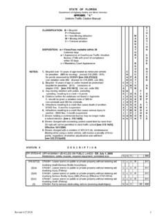
1 These Options are in addition to theStandard Ladder Rungs, Ventilated Trough and Solid Trough type Cable Rung (Available in Aluminum, HDGAF Steel and Stainless Steel) Designed for Series 1 and Series 2-5 systems. Special rung Design to accommodate stainless steel banding of cables ( Coast Guard requirement) with .438" x .720" slots. Has applications on land, vertical installation, any location where extra cable positioning/attachment is required. Strut orientation may be channel opening up, channel opening down, or alternating - standard is alternating unless specified otherwise. New Design provides combination of strut fastening and marine rung : 46A12MR-36-288 or 464G12MR-36-288 "MR" Strut rung on 12" centers with channel opening down(Note: replace "DN" with "UP" for channel opening up.)Special Rung Spacings: 4" & 18" rung spacing available upon Solid flat sheet welded into the Cable Tray above the rungs.
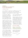
2 Standard rung spacing is 12 inches. The flat sheet may be installed under the rungs, if preferred. The flat sheet may be installed over B54 rungs slot down .Examples: 24 ASB-36-144 Flat sheet Bottom over standard rung on 12" sheet Bottom over B54 strut rung slot down on 12" spacing.(Aluminum Shown)AppendixAppendix - Bottom Design OptionsAPP-1B-Line series Cable Tray SystemsEatonAppendix9A-6006 and 9A-6007 Aluminum Mid-Span SpliceFeatures Standard for H46A, H47A and 57A straight sections. Allows random splice location. Six bolt Design furnished with standard 1/2" Stainless Steel Type 316 hardware. Furnished in pairs. Available on ladder bottoms " and 12" rung : The 9A-6006 and 9A-6007 splice is also available with B-Line 46A and 47A series cable tray systems Available on ladder bottoms only (09" and 12" rung spacing). Available on 240" (20 ) or longer span straight sections. To order add MS* to part number: Ex.
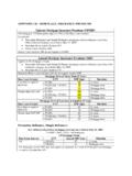
3 46 AMS09-24-288. For standard 6A or 7A fittings with H46A or H47A systems an additional pair of standard splice plates is required (9A-1006 or 9A-1007).* MS designates additional hole punches in side rail to accept mid-span pair 9A-6006 or 9A-6007 Tray: H46AH47 ATested to:Tested to: 167 lbs/ft (safety factor ) 149 lbs/ft (safety factor ) 125 lbs/ft (safety factor ) 112 lbs/ft (safety factor ) 20 ft. simple beam test 20 ft. simple beam test12" rung spacing - 36" wide12" rung spacing - 36" wideSplice: 9A-60069A-6007 Tested to:Tested to: 135 lbs/ft (safety factor ) 143 lbs/ft (safety factor ) 101 lbs/ft (safety factor ) 107 lbs/ft (safety factor ) 20 ft. simple beam test 20 ft. simple beam test mid-span splicemid-span spliceTraySeries Catalog available: H6A and H7A Fittings Ladder Bottom only (09" RS). Incorporates the 9A-6006 or 9A-6007 splice. Example: H6A-12-90HB24 or H7A-12-90HB24 Appendix - Mid Span SpliceAPP-2B-Line series Cable Tray SystemsEatonAppendixHeavy Duty Expansion Splice Plates9A-6016 and 9A-6017 (aluminum)9G-6016 and 9G-6017 (HDG steel)9SS6-6016 (stainless steel)The Heavy Duty Expansion Splice Plate is engineered to eliminate the NEMA recommended additional supportsat each expansion joint where expansion splice plates are utilized.
4 Expansion splices are common in long-runoutdoor applications, where temperature variations result in thermal expansion and contraction of the cable traysystem. The installer using the traditional expansion splice would be required to install two supports, one oneither side of the expansion splice. By utilizing the Heavy Duty Expansion Splice Plate, no additional supportsare required when the splice is placed at quarter span. NEMA VE 2 Compliant Lowest total cost of installation solution Wrap around Design that supports the side rail on the Bottom of each tray section Available in lightweight, marine-grade 6063-T6 aluminum material, hot dip galvanized steel,and stainless steel 316 for easy installation in a variety of applications Visit for detailed installation instructions Splice plate hardware included Furnished in pairs Cannot be used with solid Bottom or trough Bottom styles of cable tray.
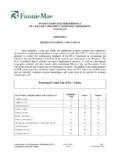
5 Heavy Duty Expansion Splice Plates are currently available with aluminum (H46A, H47A & 57A), steel (464, 476 & 574), and stainless steel (464) tray systems. These tray systems are heavy duty ladders that are ideal forlong-span, outdoor : Partent No. US8459604 B2 Aluminum heavy-duty expansion splice plates Series Catalog *9A-6016H46A9A-6016H47A9A-601757A9A-6017 * Additional field drilling is requiredSteelTray SeriesCatalog or 9SS6-60164769G-60175749G-6017 SteelAluminumAppendix - Heavy Duty Expansion SpliceAPP-3B-Line series Cable Tray SystemsEatonOptions: The 9A-6006 and 9A-6007 splice is also available with B-Line 46A and 47A series cable tray systemsNote: 24 (609mm)bonding jumper (99-1620-24) 33 slope to shed precipitants. Heavy construction - made for the industrial environment. Available in aluminum and steel; hot dip galvanized after fabrication (HDGAF ASTM A-123), 304 stainless and 316 stainless.
6 Available in flanged Design only. Fittings are in multiple piece welded construction. Expanding/Reducing HT and HX covers are not BendVertical OutsideBendHorizontalCrossHorizontalTeeC over Type83 = 2 to 3 PitchPeakedDetail7 = Flanged Aluminum2 = Flanged Steel (248, 258, 268straight sections&fittings3 = Flanged Steel (All straightsections except248, 258, 268)MaterialA=AluminumG = HDGAF ASTMA-123SS4 = 304 Stainless SteelSS6 = 316 Stainless SteelTray Width06 = 6" 09 = 9" 12 = 12" 18 = 18" 24 = 24" 30 = 30" 36 = 36" Item Description144 = 12 ft. ( m)120 = 10 ft. ( m)72 = 6 ft. ( m)60 = 5 ft. ( m)Catalog Number SelectorSpecial Purpose 2 to 3 Pitch Peaked CoversThese covers are notavailable for Series 1system or in steel witha pre-galvanized to 3 Pitch Cover Clamp Recommended for outdoor service.( ) Insert tray width (**) Insert SS4 or SS62 to 3 PitchPeakHeightTrayWidth6" 2"9" 3"12" 4"18" 6"24" 8"30" 10"36" 12"Side Rail (mm)AluminumSteelStainless Steel4(101)9A-( )-9P44 9G-( )-9P44 9**-( )-9P445(127)9A-( )-9P54 9G-( )-9P54 9**-( )-9P546(152)9A-( )-9P64 9G-( )-9P64 9**-( )-9P647(178)9A-( )-9P74 9G-( )-9P74 9**-( )-9P74 Green= Fastest shipped items Black = Normal lead-time items Red= Normally long lead-time itemsMaterial Thickness80 =.)
7 080 Aluminumstraight section125 = .125 Aluminum fittings16 = 16 Ga. Steel straight sections. 18 = 16 Ga. Steel 7 A 80 - 24 - 144 Example: Appendix - Special Purpose Peaked CoversAPP-4B-Line series Cable Tray SystemsEatonAppendix1. Armored cable .. (Article 320)2. Electrical metallic tubing .. (Article 358)3. Electrical nonmetallic tubing .. (Article 362)4. Fire alarm cables .. (Article 760)5. Flexible metal conduit .. (Article 348)6. Flexible metallic tubing .. (Article 360)7. Instrumentation tray cable .. (Article 727)8. Intermediate metal conduit .. (Article 342)9. Liquidtight flexible metal conduit .. (Article 350) 10. Liquidtight flexible nonmetallic conduit .. (Article 356)11. Metal-clad cable .. (Article 330)12. Mineral-insulated, metal-sheathed cable .. (Article 332)13. Multiconductor service-entrance cable .. (Article 338) 14. Multiconductor underground feeder and branch-circuit cable.
8 (Article 340)15. Multipurpose and communications cables .. (Article 800)16. Nonmetallic-sheathed cable .. (Article 334)17. Power and control tray cable .. (Article 336)18. Power-limited tray cable .. (Section (C) and (E)19. Optical fiber cables .. (Article 770)20. Other factory-assembled, multiconductor control, signal, or powercables that are specifically approved for installation in cable trays21. Rigid metal conduit .. (Article 344)22. Rigid nonmetallic conduit .. (Article 352)Wiring methods permitted in cable tray per the 2011 NEC Appendix - Reference Material - FormulasFormulas Allowable load:w =F96 SxL2w = load (lbs/ft)W = total load across span (lbs)F = Design stress (lbs/in2)L = span (inches)Sx = section modulus for 2 rails (in3)(see page APP-6 for Sx values)E=10 million for Alum. ( )29 million for Steel ( )Ix = moment of inertia for 2 rails (in4)(see page APP-6 for Ix values) Deflection: =5wL3384 EIx =5wL44608 EIx Stress:F =wL296Sx Deflection Multiplier (K) =deflectionw= 5L44608 EIx Max.)
9 Working Load =Max. deflectionDeflection Multiplier LegendAppendix - Reference Material - Methods PermittedAPP-5B-Line series Cable Tray SystemsEatonAppendixA -Side Rail Height B -Loading Depth C -Web Thickness D -Flange Width Design Factors:Ix = Moment of Inertia, Sx = Section ModulusB-Line Side RailABCDESx Ix Area WeightSeries Height(in.) (in.) (in.) (in.)(in.) ( ) ( ) ( ) ( ) .048 ..450 .251 ..060 ..760 .340 .060 ..385 .060 ..444 .048 .392 .320 .720 .313 .060 .655 .480 .449 .075 .670 .640 .561 .048 .392 .450 .361 .060 .655 .660 .509 .075 .670 .870 .636 .048 .392 .590 .409 .048 .643 .710 .457 .060 .655 .850.
10 569 .075 .670 .711 .048 .643 .890 .505 .060 .655 .629 .075 .670 .792 148-176 Rail OnlyAll Other Steel RailsDACDEACBBC able Tray Side RailsB-Line Side RailABCDESx Ix Area WeightSeries Height(in.) (in.) (in.) (in.)(in.) ( ) ( ) ( ) ( ) .059 .059 .067 .067 .067 .059 .061 .059 .075 .060 .070 .100 .068 .090 .065 .075 .085 .130 .075.