Transcription of APPENDIX F: STREAM ORDER AND WATERWAY …
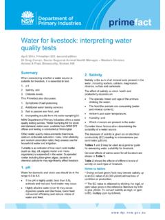
1 98 APPENDIX F: STREAM ORDER AND WATERWAY CLASSIFICATION SYSTEM STREAM ORDER Classification System I&I NSW uses the Strahler STREAM classification system where waterways are given an ORDER according to the number of additional tributaries associated with each WATERWAY (Strahler, 1952). This system provides a measure of system complexity and therefore the potential for fish habitat to be present. Figure A1 indicates the Strahler STREAM ordering process. Numbering begins at the top of a catchment with headwater ( new ) flow paths being assigned the number 1. Where two flow paths of ORDER 1 join, the section downstream of the junction is referred to as a second ORDER STREAM . Where two second ORDER streams join, the WATERWAY downstream of the junction is referred to as a third ORDER STREAM , and so on. Where a lower ORDER STREAM ( first ORDER ) joins a higher ORDER STREAM ( third ORDER ), the area downstream of the junction will retain the higher number ( it will remain a third ORDER STREAM ).
2 I&I NSW recognises 3rd ORDER streams and above as likely to display valuable fish habitat, and hence could support viable fish populations. As a result, fish passage barriers located on 3rd ORDER and above waterways should be considered for remediation. Although some exceptions apply, STREAM ORDER will also correspond with the WATERWAY classification described below, with Class 4 waterways generally being 1st and 2nd ORDER streams (and some 3rd ORDER streams), while Class 3 will generally be 3rd ORDER streams. Class 1 and 2 will be 3rd ORDER or above streams. FIGURE A1. STREAM ordering for a fictitious catchment using Strahler (1952) method. 99 WATERWAY Classification System Throughout NSW, I&I NSW applies a basic Class system to assign aquatic habitat values to waterways. As mentioned above, overlap exists between Class and Strahler s STREAM ordering system; however, specific WATERWAY characteristics feature more prominently in Class definitions.
3 Table A2 outlines the characteristics of each WATERWAY class. WATERWAY Class was one of the criteria used to prioritise road crossing sites in NSW as part of Bringing Back the Fish project. TABLE A2: I&I NSW classification of fish habitat in NSW waterways and recommended crossing type. From Fairfull and Witheridge (2003). Classification Characteristics of WATERWAY Type Minimum[1] RecommendedCrossing Type CLASS 1 Major fish habitat Major permanently or intermittently flowing WATERWAY ( river or major creek); habitat of a threatened fish species or critical habitat . Bridge, arch structure or tunnel. CLASS 2 Moderate fish habitat Named permanent or intermittent STREAM , creek or WATERWAY with clearly defined bed and banks with semi-permanent to permanent waters in pools or in connected wetland areas. Marine or freshwater aquatic vegetation is present. Known fish habitat and/or fish observed inhabiting the area.
4 Bridge, arch structure, culvert [2] or ford. CLASS 3 Minimal fish habitat Named or unnamed WATERWAY with intermittent flow and potential refuge, breeding or feeding areas for some aquatic fauna ( fish, yabbies). Semi-permanent pools form within the WATERWAY or adjacent wetlands after a rain event. Otherwise, any minor WATERWAY that interconnects with wetlands or recognised aquatic habitats. culvert [3], or ford. CLASS 4 Unlikely fish habitat Named or unnamed WATERWAY with intermittent flow following rain events only, little or no defined drainage channel, little or no flow or free standing water or pools after rain events ( dry gullies or shallow floodplain depressions with no permanent aquatic flora present). culvert [4], causeway or ford. [1] In all cases bridges are preferred to arch structures, culverts, fords and causeways (in that ORDER ). [2] High priority is given to the high flow design procedures for the design of these culverts refer to Design Considerations in Fairfull & Witheridge (2003) or engineering guidelines (Witheridge, 2002).
5 [3] Minimum culvert design using the low flow design procedures; however, high flow design and medium flow design should be given a priority where affordable (refer Witheridge, 2002). [4] Fish friendly WATERWAY crossing designs possibly unwarranted. Fish passage requirements should be confirmed with the local fisheries department/authority. 100 APPENDIX G: RECOMMENDED FISHWAY DESIGNS Information presented here is sourced from Thorncraft and Harris (2000), and Mallen-Cooper (2000). Rock-ramp fishways Rock-ramp fishways were developed as a simple and relatively low-cost alternative to more formally engineered fishway designs ( vertical slot and denil fishways). Rock-ramps are often used to overcome low barriers (< 3 m) such as weirs and road crossings, or at sites of significant STREAM channel. The structures are generally built on slopes that attempt to match the surrounding geomorphic features within the WATERWAY , with slopes of 1:20 generally employed higher in the catchment and slopes of 1:30 recommended for estuarine sites due to smaller fish size classes.
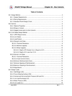
6 In this style of fishway, large rocks are placed to form a series of small pools separated by rock ridges spaced at 2 m intervals. Fish ascend the fishway by darting through sections of high water velocity occurring between the large tombstone ridge rocks, and resting in the pools created between the rock ridges. Water flows down the fishway channels, with a head differential between 70 and 100 mm occurring across each ridged depending upon the designed slope. Two variations of this form of this fishway are employed in Australia the partial-width rock-ramp fishway (Figure A3), and the full-width rock-ramp fishway (Figure A4). FIGURE A3: Conceptual drawing of a partial-width rock-ramp fishway. 101As the name implies, the partial-width rock-ramp fishway only extends part way across the width of a WATERWAY , with water directed down a defined channel; whereas a full-width rock-ramp fishway extends the entire width of a WATERWAY , with low flows being directed down a defined low-flow channel.
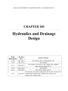
7 FIGURE A4: Conceptual drawing of a full-width rock-ramp fishway (plan view) Full-width rock-ramp fishways can easily accommodate low or high flow events, and thus are considered a more effective design compared to the partial-width rock-ramp fishway which are effectively primarily during base flow periods. On the Gloucester River (Hunter/Central Rivers CMA), modified versions of the partial-width rock-ramp fishway were employed at causeway road crossings, with the upstream exit of the fishway meeting the downstream edge of the road cap at a V depression in the road surface. Alternatively, at The River Road, Currowan Creek (Southern Rivers CMA), a full width rock ramp fishway was installed. These modified fishways provide a means for fish to reach the road surface, but fish passage remains limited to rising flows when water depth across the road surface is increased.
8 The full-width rock-ramp fishway at Skewes Crossing on the Orara River bypassed this issue with water flow and fish passage occurring beneath the road deck through a single large box culvert . 102 Vertical slot fishways Vertical slot fishways comprise a more engineered and controlled version of a rock-ramp fishway where resting pools are essentially concrete cells, with the entrance/exit to/from each of the pools being a vertical slot at either end (Figure A5). The maximum water velocity occurs as water falls through each slot, with the downstream pool acting to slow water down and provide resting areas for ascending fish. The slope of the channel and the width of each slot controls the water velocity (generally < ms-1) through each slot, thus the fishway can be designed to suit the swimming ability of particular ascending fish. FIGURE A5: Conceptual drawing of a vertical slot fishway.
9 Baffles act to control water direction and speed within the fishway, allowing fish to ascend. Vertical slot fishways have flexibility of operation over varying headwater and tailwater levels, as well as allowing fish to pass through the fishway at any depth. As a result, vertical slot fishways are considered one of the most effective fishways designs for passing a range of fish species and size classes. Vertical slot fishways are generally more expensive than a rock-ramp structures, and requires larger volumes of water to operate. 103 Denil fishways Denil fishways comprise a straight channel set with a series of near vertical U shaped baffles along the entire length (Figure A6). The main advantage of Denil fishways is that they can be built on steeper slopes (1:12) than rock-ramp or vertical slot fishways. This feature enables Denil fishways to be installed in their own right or as a retrofitting technique for older design fishways (such as chute or submerged orifice designs which were designed for Northern Hemisphere fish species) that have a slope that is too steep for most native fish to ascend.
10 Fish passage is possible for smaller species or size classes near the base of the denil inserts where water velocities are reduced. Better swimming species or larger size classes will use the remainder of the fishway to ascend. Design concessions for the Denil fishway include the requirement for high water volumes to pass through the fishway for effective operation, and functioning over a limited headwater range compared to vertical slot fishways. FIGURE A6: Conceptual layout of baffle and water movement within a Denil fishway. 104 APPENDIX H: ACTIVE FLOODGATE MANAGEMENT OPTIONS The benefits associated with active floodgate management are largely related to the frequency and duration of gate opening, and predominantly include: Improved fish passage and connectivity between estuarine and drainage habitats; Improved habitat condition, including the control of aquatic weeds; Enhanced water quality through the controlled exchange of water, which reduces acidity, iron and aluminium flocs; increased stable dissolved oxygen levels, and decreased nutrients and algal blooms; and Enhanced wetland habitats upstream (Johnston et al.)