Transcription of APPENDIX I - extranet.vdot.state.va.us
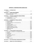
1 APPENDIX I SECTION I-1-INTRODUCTION .. I-1 SECTION I-2- BARRIER SYSTEMS AND TERMINALS .. I-2 W-Beam Guardrail General Criteria .. I-2 GR-10 Guardrail over Culvert in Low Fills .. I-4 High Tension Cable .. I-5 Concrete Barrier .. I-5 Barrier Terminals General Criteria .. I-6 GR-3 Low Tension Cable Terminal .. I-7 GR-6 W-Beam Buried In The Cut Slope Terminal .. I-7 GR-7 W-Beam Flared Terminal .. I-7 GR-9 W-Beam Tangent Terminal .. I-8 GR-11 W-Beam Run-Off Only Terminal .. I-9 Thrie-Beam Bull Nose Barrier .. I-9 MB-9A Turned Down Concrete Median Barrier Terminal .. I-10 Impact Attenuators .. I-10 SECTION I-3 BARRIER INSTALLATION CRITERIA Barrier Warrants .. I-13 Fixed Objects Within Deflection Area .. I-15 Ponds or Other Bodies of Water.
2 I-15 Short Gaps .. I-15 Barrier Type Selection .. I-15 Determining Location of the Ends Of Guardrail .. I-18 Asphalt Paving Under Guardrail .. I-20 Asphalt Curbs .. I-20 Guardrail Installation Adjacent to Curb .. I-21 SECTION I-4 FIXED OBJECT ATTACHMENTS (FOA) AND BRIDGE GUARDRAIL ATTACHMENTS (BRGR) FOA .. I-25 BRGR .. I-25 Entrances or Connections Adjacent to A Bridge .. I-25 SECTION I-5 SAFETY/MAINTENANCE PROJECTS .. I-26 LIST OF FIGURES Page Figure I-2-1 Dimensions For Crash Cushion .. I-12 Table I-3-1 Determining Warrants For Roadside Barriers .. I-14 Table I-3-2 Typical Barrier Selection and Placement .. I-17 Figure I-3-1 - Barrier Length of Need Determination .. I-18 Table I-3-3 Design Parameters For Roadside Barrier Layout.
3 I-19 Figure I-3-2 Suggested Slopes For Approach Barriers .. I-20 Figure I-3-3 Typical Curb Offset Layout For A Tangent Guardrail Terminal .. I-22 INTRODUC Traffic Barmedian baoccurring leaving theroadway sbarrier will drainage hexcessive;many year When guaincluding hassessmenTraffic Engthe existingVDOT Roa 1. 2. 3. For definitRoadwaysProjects. * Rev. 1/18 CTION rriers discuarrier and and shoulde roadway whould be exnot be reqheadwall, e however, rs should noardrail is wheavy mainnt on all exgineering Dg guardrail ad and BridWhen loline of rasubstanreplacedless thalimits is line of raWhen lassociaWhen amust cMASH rail sysSecondtions of R, see VDO 8 Sussed in ththeir assocd only be would be mxamined touired ( etc.)
4 The ithe fact thot be overloholly or pantenance axisting guarDivision IIMshall be upge Standarocated witail extends ndard line od including an 60% is wto be upgrail even whlocated wiated with pany road iscomply wit(Manual fostems. (Fdary StreetRRR utilizinT s Road D APSECTION I-is appendixciated termused whermore severe determine flattening ainitial cost hat a barriooked. artially withand RRR rdrail system-TE-366 fopgraded to rds for the hin the prooutside theof rail withiterminals within the aded. Conhen less thaithin the ppermitted las acceptedth current or AssessFor VDOT t Acceptanng FederalDesign ManPPENDIX I1- INTRODx include wminals, do re the resue than the cthe feasibia fill slope, to eliminater installatin the projprojects, thms and comor upgrade the latest sfollowing soject limitse project limin the projeand upgraproject liminsideration an 60% is wproject limand develod into the Standarding Safetyapproved ce Require Funding nual, AppenDUCTION w-beam gunot prevenult of strikinconsequencility of adjusremoving ate the neeion will reqject limits fhe engineemponents iwarrants.))
5 Standard inituations: *s of a consmits with mect limits, ded to meits, then onshould be within the prmits of traopment prostate roads and muy HardwareDevelopeements (SSon Nationndix A, Secuardrail, cant collisionsng a fixed ce of strikinsting site fea hazardoused for a baquire mainfor any coer shall peincluding teIf warranten accordancstruction pmore than 6then the eet the currnly the rail given to uproject limitsnsportatioojects. dway systust includee) approveer ConstruSAR) govenal Highwaction A-4 Gble, and cos or injurieobject hazg the barrieeatures so ts object suarrier may tenance construction erform a germinals. Red by IIM-Tce with the project. Wh0% of the eentire run srent Standawithin the pgrading thes.
6 On improvetem, all gue NCHRP ed terminauction Planern.) ay System Guidelines foI-1 oncrete es from zard or er. The that the ch as a appear osts for project, uardrail Refer to TE-366, current hen the existing shall be ards. If project e entire ements uardrail 350 or als and ns, the (NHS) or RRR I-2 SECTION I-2- BARRIER SYSTEMS AND TERMINALS W-BEAM GUARDRAIL GENERAL CRITERIA During NEW CONSTRUCTION, always install to the current Standard heights. New and existing guardrail within the project limits must meet NCHRP 350 or MASH requirements. All guardrail shall be replaced or upgraded in accordance with Section I-1. All w-beam guardrail panels shall be lapped in the direction of traffic. With two-way traffic, the laps on the right side of traffic are to be in the direction of traffic or toward the downstream end.
7 Refer to the Road and Bridge Standards for transition designs between flexible and more rigid systems. All roadside safety devices are to be equipped with identification numbers as per Code of Virginia * GR-2 STRONG POST W-BEAM GUARDRAIL For GR-2, the minimum height is 27 3/4 to the top of the rail with a maximum height of 28 3/4 . When checking the height on a length of GR-2, measure at increments of 50 where there is a rail splice at a post. Refer to the GR-INS Standard for measuring w-beam guardrail based on location on a slope. The wood and composite blockouts can be used interchangeably within a single run of guardrail for new installations, replacements, and upgrades. When existing 6 x8 wood or composite blockouts are replaced, the blockouts shall include routing to prevent blockouts from rotating.
8 When wood posts with wood blockouts are used, they shall have TWO nails (one on each side) to prevent rotation of blockouts. No metal blockouts are to be replaced in-kind or installed new, and no washers will be used. When posts are removed and are to be reused, the Post shall meet the current standard length. They shall be reused only with Standard wood or composite blockouts. When resetting rail, the posts shall be removed and the holes backfilled prior to reinstalling the posts. The height of the rail shall be measured to ensure it meets the current VDOT Road and Bridge Standards. See Section 3 for guardrail installation adjacent to curb. * Rev.
9 7/15 I-3 MB-3 STRONG POST MEDIAN BARRIER W-BEAM GUARDRAIL MB-3 is double sided GR-2 that consists of a line of single posts with a blockout and w-beam guardrail on each side designed for use in the median when the back side of the system is within the clear zone of the opposing traffic. MB-5 WEAK POST MEDIAN BARRIER W-BEAM GUARDRAIL MB-5 is double sided GR-8 that consists of a line of single posts with a w-beam guardrail on each side designed for use in the median when the back side of the system is within the clear zone of the opposing traffic. MB-5 must be transitioned to MB-3, per the Standards, prior to a terminal or attaching to an FOA. For raising existing GR-2 rail height only, a 2 , 3 or 4 vertical adjustment of the GR-2 (steel post only) rail is allowed by adjusting the blockout and redrilling the post provided the post is acceptable to use.
10 Centerline of holes shall be no closer than 2 to another hole and no less than 2 from top of post. Hole diameter shall be 3/4 . For 4 adjustment, 2 bolts shall be used; one above the other with centerlines of holes 4 apart. Blockouts must be able to accommodate the additional bolt for a 4 adjustment. See detail below. If the GR-2 rail cannot be adjusted to the current Standard GR-2 height, then the guardrail is to be reset. I-4 GR-3 LOW TENSION CABLE GUARDRAIL For GR-3, the minimum height is 27 to the top cable with a maximum height of 28 . Measure the height at the posts in increments of 48 feet. When GR-3 is hit, the cable will typically drop rendering the entire run nonfunctioning until it is repaired.