Transcription of Application Guide Contactors for capacitor switching
1 Application Guide Contactors for capacitor switching 1 10/03/2010 09:57:25. 3 18/03/2010 17:09:30. Contactors for capacitor switching Contents General Reminder of capacitor Transient Conditions .. 2. Steady State Condition Data .. 2. Consequences for the Contactors .. 2. ABB Solutions for capacitor Bank switching The Contactors , equipped with Damping Resistors .. 3. The Contactors .. 3. The and Standard Contactors .. 3. Contactors , equipped with Damping Resistors Application .. 4. Description .. 4. Selection Table .. 4. Ordering Details .. 5. Technical Data .. 6. Main Accessories .. 7. Terminal Marking and Positioning.
2 8. Dimensions .. 9. Contactors Application .. 12. Selection Table .. 12. Ordering Details .. 13. Technical Data .. 14. Main Accessories .. 15. Terminal Marking and Positioning .. 16. Dimensions .. 17. and Standard Contactors Application .. 18. Selection Table .. 18. Ordering Details .. 19. Main Accessories .. 20. Selection Examples Application and possibilities .. 22. Calculation and Dimensioning inrush current peak and frequency .. 23. Anti resonance Inductances .. 31. Installation studies .. 32. 1. 1 SBC101140C0202. Contactors for capacitor switching AC-6b Utilization Category according to IEC 60947-4-1.
3 capacitor Transient Conditions In Low Voltage industrial installations, capacitors are mainly used for reactive energy correction (raising the power factor). When these capacitors are energized, overcurrents of high amplitude and high frequencies (3 to 15 kHz) occur during the transient period (1 to 2 ms). The amplitude of these current peaks, also known as " inrush current peaks", depends on the following factors: The network inductances. The transformer power and short-circuit voltage. The type of power factor correction. There are 2 types of power factor correction: fixed or automatic. Fixed power factor correction consists of inserting, in parallel on An automatic power factor correction system, on the other hand, the network, a capacitor bank whose total power is provided by the consists of several capacitor banks of identical or different ratings assembly of capacitors of identical or different ratings.
4 (several steps), energized separately according to the value of the The bank is energized by a contactor that simultaneously supplies power factor to be corrected. all the capacitors (a single step). An electronic device automatically determines the power of the steps The inrush current peak, in the case of fixed correction, can reach to be energized and activates the relevant Contactors . 30 times the nominal current of the capacitor bank. The inrush current peak, in the case of automatic correction, de- pends on the power of the steps already on duty, and can reach 100 times the nominal current of the step to be energized.
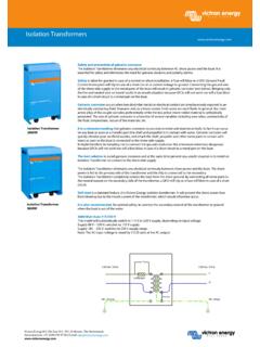
5 E1178D. E1179D. Single-step capacitor bank scheme Multi-step capacitor bank scheme Use the contactor ranges. Use the or contactor ranges. Steady State Condition Data The presence of harmonics and the network's voltage tolerance lead to a current , estimated to be times the nominal current In of the capacitor , permanently circulating in the circuit. Taking into account the manufacturing tolerances, the exact power of a capacitor can reach times its nominal power. Standard IEC 60831-1 Edition 2002 specifies that the capacitor must therefore have a maximum thermal current IT of: IT = x x In = x In Consequences for the Contactors To avoid malfunctions (welding of main poles, abnormal temperature rise, etc.)
6 , Contactors for capacitor bank switching must be sized to withstand: A permanent current that can reach times the nominal current of the capacitor bank. The short but high peak current on pole closing (maximum permissible peak current ). Contactor Selection Tool for capacitor switching In a given Application , if the user does not know the value of the inrush current peak, this value can be approximately calculated using the formulas given on the pages "Calculation and dimensioning". Alternatively by the CAPCAL Selection Tool, available on the ABB Website: right menu: "Support". search: "Online Product Selection Tools".
7 Select: " Contactors : AC-6b capacitor switching ". This program allows the calculation of these peaks and gives the references of the ABB. Contactors according to the installation specifications. This calculation is valid for one or several capacitor banks. 2. 1 SBC101140C0202. Contactors for capacitor switching The ABB Solutions ABB offers 3 contactor versions according to the value of the inrush current peak and the power of the capacitor bank. Contactors for capacitor switching (UA to UA ) with insertion of damping resistors. The insertion of damping resistors protects the contactor and the capacitor from the highest inrush currents.
8 1 SBC5 9144 4F0302. 1 SBC5 8776 4F0301. 1 SBC5 8777 4F0301. 1 SBC5 8779 4F0301. Contactors for capacitor switching (UA 16 to UA 110). Maximum permissible peak current < 100 times the nominal rms current of the switched capacitor . 1 SBC5 9169 4F0303. 1 SBC5 8009 3F0303. 1 SBC5 8078 3F0303. 1 SBC5 8010 5F0303. and Standard Contactors (A 12 to A 300 and AF 50 to AF 750). Maximum permissible peak current < 30 times the nominal rms current of the switched capacitor . 1 SFC1 0103 4F0201. 1 SBC5 9169 4F0303. 1 SBC5 8075 3F0301. 1 SBC5 7324 2F0301. 3. 1 SBC101140C0202. 3-pole Contactors for capacitor switching Unlimited Peak current .
9 Application The Contactors can be used in installations in which the peak current far exceeds 100 times nominal rms current . The Contactors are delivered complete with their damping resistors and must be used without additional inductances (see table below). The capacitors must be discharged (maximum residual voltage at terminals 50 V) before being re-energized when the Contactors are making. Their electrical durability is 250 000 operating cycles for Ue < 500 V and 100 000 operating cycles for 500 V < Ue < 690 V. Description The Contactors are fitted with a special front mounted block, which ensures the serial insertion of 3 damping resistors into the circuit to limit the current peak on energization of the capacitor bank.
10 Their connection also ensures capacitor precharging in order to limit the second current peak occurring upon making of the main poles. Operating principle The front-mounted block mechanism of the Contactors ensures: early making of the auxiliary "PA" poles with respect to the main "PP" poles automatic return to the open position of the auxiliary "PA" poles after the main poles are closed. When the coil is energized, the early making auxiliary poles connect the capacitor to the network via the set of 3 resistors. The damping resistors attenuate the first current peak and the second inrush current when the main contacts begin to make.